Table of Contents
Advertisement
Quick Links
Energy Technology srl
Operating office :
Via della Solidarieta 2/1
40056 Valsamoggia – Loc. Crespellano (BO) – Italy
Ph : + 39 051 6656 611 Fax : +39 051 6656 677
ocem@ocem.com
VAT Nr : IT 031 4821 1208
Single- phase Compact SCR-type
Constant Current Regulator
–
www.ocem.com
a division of Energy Technology srl
DIAM3100
Installation & maintenance
Compliance with standards:
ICAO Aerodrom design manual, part 5
IEC (61822)
Advertisement
Table of Contents

Subscribe to Our Youtube Channel
Related Manuals for OCEM AUGIER energy DIAM3100 Series


Summary of Contents for OCEM AUGIER energy DIAM3100 Series
- Page 1 Via della Solidarieta 2/1 40056 Valsamoggia – Loc. Crespellano (BO) – Italy Ph : + 39 051 6656 611 Fax : +39 051 6656 677 – ocem@ocem.com www.ocem.com VAT Nr : IT 031 4821 1208 a division of Energy Technology srl Installation &...
- Page 2 DIAM3100©2012 AUGIER SA.
-
Page 3: Record Of Change
DIAM3100©2012 AUGIER SA. RECORD OF CHANGES Rev. Pages Description From S/N App. Date First issue 30/11/12 New codification >2018 20/02/18 New logo 23/05/18... -
Page 4: Warranties
DIAM3100©2012 AUGIER SA. WARRANTIES Guarantee AUGIER’s goods are guaranteed for one year from delivery date on the signed delivery note, and are guaranteed to be free from defects in materials used, design and manufacture. The guarantee covers repair, modification or replacement of parts or products recognised to be defective, in the shortest possible time, at AUGIER’s cost, provided always that the goods have been properly handled and stored prior installation, properly installed and properly operated after installation. -
Page 5: Safety
DIAM3100©2012 AUGIER SA. SAFETY Safety precautions This equipment is normally used or connected to circuits that may employ dangerous and lethal voltages. Extreme caution should be exercised by operating or maintenance people when working on or with this equipment. See IEC 61820 & 61821 standard (CCR type IEC), or FAA AC150/5340-26 advisory circular (CCR type FAA), concerning safety rules and precautions. - Page 6 DIAM3100©2012 AUGIER SA.
-
Page 7: Table Of Contents
DIAM3100©2012 AUGIER SA. TABLE OF CONTENTS RECORD OF CHANGE ……………………………………………………………………………………………… I-2 WARRANTIES …………………………………………………………………………………………………………… I-3 SAFETY ……………………………………………………………………………………………………………….….. I-4 TABLE OF CONTENTS ……………………………………………………………………………………………… I-5 DESCRIPTION _______________________________________________________ I-11 OVERVIEW ______________________________________________________________________ I-11 MECHANICAL DESCRIPTION _______________________________________________________ I-12 I.2.1 DESCRIPTION ________________________________________________________________ I-12 I.2.2 GENERAL MECHANICAL FEATURES _____________________________________________ I-12 I.2.3 STORAGE CONDITIONS _______________________________________________________ I-12 I.2.4... - Page 8 DIAM3100©2012 AUGIER SA. OPTIONS ________________________________________________________________________ I-24 I.7.1 EARTH FAULT DETECTOR (EFD) ________________________________________________ I-24 I.7.2 CUT OUT AND EARTHING PLATE ________________________________________________ I-25 I.7.2.1 Normal position : _____________________________________________________________ I-25 I.7.2.2 Safety position: ______________________________________________________________ I-25 I.7.3 OUTPUT LIGHTING ARRESTORS ________________________________________________ I-26 I.7.4 CASTERS ____________________________________________________________________ I-26 I.7.5 BURNT LAMP DETECTION: _____________________________________________________ I-26 I.7.6...
- Page 9 DIAM3100©2012 AUGIER SA. COMMISSIONING __________________________________________________ III-44 III.1 PROCEDURE ___________________________________________________________________ III-44 III.2 TESTS _________________________________________________________________________ III-45 III.2.1 SHORT-CIRCUIT TESTS _______________________________________________________ III-45 III.2.2 OVERLOAD TESTS ___________________________________________________________ III-45 III.2.3 OPEN-CIRCUIT TEST _________________________________________________________ III-45 MAINTENANCE __________________________________________________ IV-46 IV.1 FORMALISATION ________________________________________________________________ IV-46 IV.2 PREVENTIVE ___________________________________________________________________ IV-46 IV.2.1 FIRST MONTHS ______________________________________________________________ IV-46 IV.2.2...
- Page 10 DIAM3100©2012 AUGIER SA. ABBREVIATIONS Abbreviation Definition Ampere Alternating Current Brightness Constant Current Regulator Direct Current High Voltage Isolation Transformer Lamp Fault Detector Low Voltage Out of order Volt Volt-Ampere I-10...
-
Page 11: Idescription
DIAM3100©2012 AUGIER SA. DESCRIPTION OVERVIEW DIAM3100 series CCRs are stackable fully static devices controlled by two thyristors (anti-parallel mounting type dimmer). They are designed to maintain a constant, pre-displayed and adjustable output current independently from the load and power supply fluctuations. They are intended to offer a low voltage device, thus ensuring that voltage will not exeed 1000V on either side of the CCR. -
Page 12: Mechanical Description
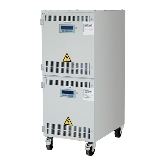
DIAM3100©2012 AUGIER SA. MECHANICAL DESCRIPTION I.2.1 DESCRIPTION Each CCR is housed in a cabinet fitted with removable lifting rings. The frame has two distinct parts: a control part (in front) and a power compartment (at the back). • The Control part of the CCR contains all the components connected to the power supply with, for example, the thyristors and associated driver boards, the master switch, the LV fuses and connection terminals. -
Page 13: Dimensions
DIAM3100©2012 AUGIER SA. I.2.4 DIMENSIONS I-13... - Page 14 DIAM3100©2012 AUGIER SA. Stacked CCRs : I-14...
-
Page 15: Electrical Description
DIAM3100©2012 AUGIER SA. ELECTRICAL DESCRIPTION I.3.1 BLOCK DIAGRAMS See paragraph I.5 for the device operating description I.3.1.1 Overview: Interfaces Measuring Control & Board Monitoring Input Thyristors LV/HV Output circuits dimmer Transformer circuits I.3.1.2 Electronic: Keyboard Display Control thyristors Main power supply 208V~ to 480V~ board DSP FRONT BOARD... -
Page 16: General Electrical Features
DIAM3100©2012 AUGIER SA. I.3.3 GENERAL ELECTRICAL FEATURES • Power supply voltage: Single phase: 220, 230, 240, 380, 400 or 415 Vac, +/-10% (IEC), 50 Hz 5%. • Maximum rated current: 6.6 A • Number of Brightness Levels: maximum 8, adjustable. •... -
Page 17: Instructions For Use
DIAM3100©2012 AUGIER SA. INSTRUCTIONS FOR USE I.4.1 USER INTERFACE Operating mode: Stop mode : Io:0.00A STOP stop local auto menu Preferred information displayed: they can be changed by a long press on the “STOP” key, meanwhile the CCR is in Stop mode. The choice can be : •... -
Page 18: Control
DIAM3100©2012 AUGIER SA. Alarms and Warnings: Alarm : (the CCR failed to supply the load); for example, the CCR is stopped by a loop open circuit : ALARM: I<<Open Cir. reset Cancel fault(s) Warning : (the CCR doesn’t stop; warning is only indicative); It is the case for EFD and LFD faults. Alphanumeric display: VFD display (16 x 140 pts) : upper text provide data information, and lower text the key definition. -
Page 19: Local Information Feedback
DIAM3100©2012 AUGIER SA. I.4.3 LOCAL INFORMATION FEEDBACK Alphanumeric display: • The display shows the RMS current flowing in the loop and the selected brightness (preferably). In the “Monitoring” menu, the following information is shown: • Uo: RMS output voltage in Vrms •... -
Page 20: Configuration Software Utility
DIAM3100©2012 AUGIER SA. I.4.1 CONFIGURATION SOFTWARE UTILITY A software has been developed to set all parameters in the CCR. This software named ALIZE4100 can be download using the following link: http://www.augier.com/soft/ALIZE4100.exe I-20... -
Page 21: Operation
DIAM3100©2012 AUGIER SA. OPERATION The “Parameter Access” function must be activated before changing parameters, in order to avoid unwanted changes. Pressing the menu touch, the display shows: Monitoring then scroll through the top-level menu items using the keys. When the “Options” item is shown like: Options press OK to go into the “Options”... -
Page 22: Configuration
DIAM3100©2012 AUGIER SA. I.5.1 CONFIGURATION The “Configuration” menu is used to define the basic parameters of the CCR (for example when replacing the main board): • Rated mains voltage in Vrms: 240 • Rated power in KW : 6.5 • Number of brightness (Including B0): from 1 to 8 •... -
Page 23: Overcurrent
DIAM3100©2012 AUGIER SA. I.5.3.3 “Overcurrent”: Overcurrent protection is activated if the output current goes above a defined value for a defined period. There are three adjustable Overcurrent levels: Setting current levels I>> Level 1, I>> Level 2, I>> Level 3, Duration IL1, Duration IL 2, Duration IL 3 : Go into the menu “Alarms and Warnings”... -
Page 24: Sub-Assemblies
DIAM3100©2012 AUGIER SA. SUB-ASSEMBLIES I.6.1 LOAD ADAPTATION The main function of the load adaptation device is to adjust the power of the CCR to the installed power of the lighting loop.. This tapping can be accessed from the back of the CCR, dismonting the rear panel. I.6.1.1 Adaptation to load: The transformer comprises output terminals which allow load settings from 12.5% (1/8 load) to 100% (4/4). -
Page 25: Cut Out And Earthing Plate
DIAM3100©2012 AUGIER SA. I.7.2 CUT OUT AND EARTHING PLATE AUGIER’s experience regarding CCRs has been used to simplify the HV compartment and maintenance operations to the maximum. With that option, the CCR is equipped with an cut-out and earthing plate, using two jumpers which allows to carry out all maintenance and measurement operations, without unscrewing any load terminal or earth connection, and without requiring any special tools. -
Page 26: Output Lighting Arrestors
DIAM3100©2012 AUGIER SA. I.7.3 OUTPUT LIGHTING ARRESTORS This option consists of two lighting arrestors, which protect the CCR at each end of the loop. Current discharge is conducted through the CCR’s main earth link, which must be of sufficient gauge. If a particularly large current flow occurs (e.g. -
Page 27: Wig Wag
DIAM3100©2012 AUGIER SA. Press OK to start initialisation. The message “ Wait please...” flashes meaning that data collection is in progress. When the message stops flashing, data collection has been completed. The number of fault lamps can be seen in the “Monitoring” menu Two comparison levels (warnings level 1 &... - Page 28 DIAM3100©2012 AUGIER SA. I-28...
-
Page 29: Installation
DIAM3100©2012 AUGIER SA. INSTALLATION II.1 PREPARATION II.1.1 EQUIPMENT RECEPTION II.1.1.1 Equipment delivered: The following are delivered with the CCR: ▪ The “Installation and Maintenance” instructions manual for the device ▪ Factory test report for the device II.1.1.2 Checking the equipment: When the device is received, check that the frame and its components (in particular the electronic and LV units) are in good mechanical condition with no distortion or signs of impact. -
Page 30: Ii.1.3 Device Location
DIAM3100©2012 AUGIER SA. II.1.3 DEVICE LOCATION In deciding the permanent operating location for the device, the following points must be kept in mind: ▪ An easy access must be kept to the front door with no obstruction. ▪ CCRs can be placed side-by-side, or stacked one on top of the other. ▪... -
Page 31: Ii.1.5 Checking The Installation
DIAM3100©2012 AUGIER SA. II.1.5 CHECKING THE INSTALLATION Checking the suitability of the electrical installation in which the CCR is to be integrated, the following points must be observed: II.1.5.1 Single phase power supply : This must be compatible with the electrical characteristics of the device as shown on the rating plate and factory test report. -
Page 32: Ii.2 Connections
DIAM3100©2012 AUGIER SA. II.2 CONNECTIONS II.2.1 POWER AND EARTH N.B.: before making any connections, make sure the installation is turned OFF. II.2.1.1 LV supply: Connection to the mains is made at the rear of the CCR, by mean of the two screw terminals. The power cable run through the hole. -
Page 33: Ii.2.1.3 Lighting Loop
DIAM3100©2012 AUGIER SA. II.2.1.3 Lighting loop: • Connect the two load cables to the “HV1” and “HV2” terminals on the two connectors • If it exists, connect the cable screen (strap or braided) to the ground clamp. Load terminal HV2 Load terminal HV1 Ground clamp (for cables’screens) -
Page 34: Ii.2.2 Remote Control Configuration
DIAM3100©2012 AUGIER SA. II.2.2 REMOTE CONTROL CONFIGURATION Connections to the control system is made at the rear of the CCR: II.2.2.1 Connectors: ETHERNET 1 ETHERNET 2 (OPTION) (OPTION) JBUS RS485 2 JBUS RS485 1 (OPTION) (STANDARD) SOURIAU CONNECTORS (OPTION) II.2.2.1 Remote control possibilities: RS485/RS422 RS485/RS422 ETHERNET 1... -
Page 35: Ii.2.2.1 Rs485/Rs422 Jbus Link
DIAM3100©2012 AUGIER SA. II.2.2.1 RS485/RS422 JBUS link: Each serial link is equipped with two SubD 9-pin (1 female and 1 male sockets). The links are electrically insulated from all the other circuits: Sub D connectors: RS422/RS485 Pin Type function Output Output Input Input... - Page 36 DIAM3100©2012 AUGIER SA. Serial link parameters: The asynchronous serial links are defined as follows: Preferred parameters : 9600 baud, 8 data bits, 1 stop bits, no parity. JBUS protocol with Id=1 at delivery. It is possible to change the speed and the ID in the “Serial Link” menu: •...
-
Page 37: Ii.2.2.2 Ethernet Link
DIAM3100©2012 AUGIER SA. II.2.2.2 Ethernet link: Interface board connections: DIAM3100 CCR can be equipped with one or two Ethernet interfaces. The used protocol is MODBUS TCP (port 502). Supplied functions are : function 3 (number of words <= 100), function 6.and function 16 (number of words =1) Slave ID = 1. -
Page 38: Ii.2.2.1 Souriau Multiwire Remote Control With 20 To 60Vdc Control Supply
DIAM3100©2012 AUGIER SA. II.2.2.1 SOURIAU multiwire remote control with 20 to 60Vdc control supply This relay board is used for SOURIAU circulars connectors, 12 and 19 pins. II.2.2.1.1 Control (20 to 60 Vdc only) : Terminal T.Bloc Function SOURIAU Pin Type B1 control 12b/9 Input voltage with respect to C... -
Page 39: Ii.2.2.1.3 Wiring Remote Control Voltage Configuration
DIAM3100©2012 AUGIER SA. II.2.2.1.3 Wiring remote control voltage configuration The DIAM CCR can be remotely controlled either by an external voltage (20 to 60 VDC positive or negative), or by “free potential” contacts (internal power supply 30VDC from the CCR). This choice is made by the values at address 70 in the Jbus table. -
Page 40: Ii.2.2.2 Circuit Selector
DIAM3100©2012 AUGIER SA. II.2.2.2 Circuit selector: External CS : The DIAM CCR has two electrical interlock terminals, terminal S1 and S2 , located at the right rear of the CCR, which must be connected to the door contact and circuit selector interlock. -
Page 41: Ii.3 Adjusting The Ccr
DIAM3100©2012 AUGIER SA. II.3 ADJUSTING THE CCR II.3.1 ADAPTATION TO LOAD Adjusting the CCR output power to that installed, using the load plate : This can be done by moving the load setting wires between 1/8 and 8/8. For example, if the load is equivalent to 60% of the rated power of the CCR, the setting is to the nearest value above, i.e. -
Page 42: Ii.3.2 Parameter Modification
DIAM3100©2012 AUGIER SA. II.3.2 PARAMETER MODIFICATION Preferably, and according to the CCR, the parameters are pre-set in the factory as ordered, so it is not necessary to reconfigure them during device installation and commissioning. II.3.2.1 Preferred configuration values: The preferred configuration (if no precision on orders, or in case of new mother board) is as follow : •... -
Page 43: Ii.3.2.2 Brightness Values
DIAM3100©2012 AUGIER SA. II.3.2.2 Brightness values: See paragraph I.5.2 If the CCR does not supply the desired current, either it is in overload or the load contains transformers with open secondaries (missing or burnt lamps) II.3.2.3 Value of “Open Circuit” protection level: See paragraph I.5.3.2 II.3.2.4 Value of “Overcurrent”... -
Page 44: Commissioning
DIAM3100©2012 AUGIER SA. COMMISSIONING After that all installation operations defined in the previous section have been completed, the DIAM3100 CCR can be commissioned. III.1 PROCEDURE 1. Set the tapping as shown in § II.3.1 2. Close the fuse box master switches 3. -
Page 45: Iii.2 Tests
DIAM3100©2012 AUGIER SA. III.2 TESTS III.2.1 SHORT-CIRCUIT TESTS DO NOT carry out this test if there is any doubt about the operation of the CCR, or if there is a fault or breakdown. 1. Switch off the CCR from the power. 2. -
Page 46: Maintenance
DIAM3100©2012 AUGIER SA. MAINTENANCE IV.1 FORMALISATION To follow maintenance procedures correctly, the following points must be observed: Create a maintenance file containing the headings “Date”, “Time”, “Maintenance Engineer”, “CCR ▪ reference”, “Problem definition”, “Solution applied”, and “Time spent” ▪ The spare parts monitoring sheet (with their control numbers) should be completed if necessary. ▪... -
Page 47: Iv.3 Corrective
DIAM3100©2012 AUGIER SA. IV.3 CORRECTIVE Motherboard fuses FUSES 1A IV.3.1 COMPONENT LAYOUT IV.3.1.1 Door components Mother board Relay board Interface board IV-47... -
Page 48: Iv.3.1.2 Lv Components
DIAM3100©2012 AUGIER SA. IV.3.1.2 LV components Main Main Inductor contactor breaker Thyristors board Thyristors Measurement board Aux. T2 transformer EFD board EMI filter board IV.3.1.3 HV components Main transformer resistors and capacitor Lightning arrestors IV-48... -
Page 49: Iv.3.2 Fault Diagnosis
DIAM3100©2012 AUGIER SA. IV.3.2 FAULT DIAGNOSIS See paragraph I.5.3 for a description of the following protections. IV.3.2.1 LV power fault: Symptom Fault Action The CCR has stopped LV power fault Check the voltage level of the LV power supply The message: Check parameter settings in the “Configuration”... -
Page 50: Iv.3.2.3 "Overcurrent" Fault
DIAM3100©2012 AUGIER SA. IV.3.2.3 “Overcurrent” fault: Symptom Fault Action The CCR has stopped Output current > programmed level Large load decrease on the loop caused by circuit switching The message: Overload combined with load Check the adaptation of the load “ALARM : I >>... -
Page 51: Iv.3.2.4 Other Faults
DIAM3100©2012 AUGIER SA. IV.3.2.4 Other faults Symptom Fault Action Output current insufficient with load Overload Check the adaptation of the load plate set to a position less than 8/8 plate to the loop power The message Large number of ITs open Check the number of ITs open due to missing or fault lamps “Warning: Regulation error”... - Page 52 DIAM3100©2012 AUGIER SA. Symptom Fault Action “WARNING : LFD level 1” Possible output regulated current Replace burnt lamps. instability. Check warning thresholds. “WARNING : LFD level 2” Possible loss of CAT conditions. Perform function learning again. “WARNING : Meas. lamps” No output voltage measurement.
-
Page 53: Iv.4 Verification Procedures
DIAM3100©2012 AUGIER SA. IV.4 VERIFICATION PROCEDURES IV.4.1 THYRISTORS The state of the thyristors can be checked as follows using an ohmmeter: ▪ Between pin 1 and pin 2, and between pin 3 and pin 1 : Several M otherwise the Thyristors are in short-circuit ... -
Page 54: Iv.5 Spare Parts List
DIAM3100©2012 AUGIER SA. IV.5 SPARE PARTS LIST CCR DIAM3100: REFERENCES Mains Désignations voltage 1 kVA 2.5 kVA 4 kVA 5 kVA 6.5 kVA 10x38 10A gG 10x38 16A gG 10x38 25A gG 14x51 32A gG 14x51 40A gG 220/240V 10.05768 10.05891 10.17586 10.05894... - Page 55 DIAM3100©2012 AUGIER SA. REFERENCES Mains Désignations voltage 1 kVA 2,5 kVA 4 kVA 5 kVA 6,5 kVA 220V 10.21529 Auxiliary 230V transformer T2 240/415V 10.21529 LV L. Arrester DS41-400 10.19975 HV L. Arrester CEA3 10.17854 PF1, PF2 R1 (MDT plate) 47kOhms 28W 13x70 10.10432 R2 (MDT plate) 47kOhms 28W 13x70 10.10432...
-
Page 56: Appendix A: Diagram
DIAM3100©2012 AUGIER SA. APPENDIX A: DIAGRAM V-56... -
Page 57: Appendix B: Jbus Table
DIAM3100©2012 AUGIER SA. APPENDIX B: JBUS TABLE Adr. R/W Mode Memory Label Detail Bit clear Bit set Default Comments Value Warnings Bit0 Stop Start Main switch status Bit1 Pb power line Power supply over range Bit2 Pb EFD Level 1 or Level 2 or EFD board defect Bit3 Pb current... - Page 58 DIAM3100©2012 AUGIER SA. Adr. R/W Mode Memory Label Detail Bit clear Bit set Default Comments Value Heat sink temperature Only for DIAM4200 EFD board status Bit0 Communication error Bit1 Internal error Interface board status Bit0 Communication error Bit1 Internal error Eeprom Status flags Bit0...
- Page 59 DIAM3100©2012 AUGIER SA. Adr. R/W Mode Memory Label Detail Bit clear Bit set Default Comments Value *KΩ(10KΩ to 10MΩ) R/W Sup Eeprom R Level EFD1 1000 *KΩ(10KΩ to 10MΩ) R/W Sup Eeprom R Level EFD2 R/W Sup Eeprom Level 1 Overcurrent *10mA (0 to 9Arms) R/W Sup Eeprom...
- Page 60 DIAM3100©2012 AUGIER SA. Adr. R/W Mode Memory Label Detail Bit clear Bit set Default Comments Value Without “ON” order With “ON” order Run Order “ON” R/W Sup Eeprom Parameters 1 Bit0 Bit1 Run to B0 Run to B1 Default brightness Bit2 Live Voltage Current flow in the loop...
- Page 61 DIAM3100©2012 AUGIER SA. Adr. R/W Mode Memory Label Detail Bit clear Bit set Default Comments Value Eeprom Brightness B3 time clock H2, H1 see note 1 Eeprom Brightness B3 time clock H0, M see note 1 Eeprom Brightness B4 time clock H2, H1 see note 1 Eeprom Brightness B4 time clock...
- Page 62 DIAM3100©2012 AUGIER SA. Adr. R/W Mode Memory Label Detail Bit clear Bit set Default Comments Value R/W Sup Eeprom Memory 0 lamps B0 0 to 1000 R/W Sup Eeprom Memory 0 lamps B1 0 to 1000 R/W Sup Eeprom Memory 0 lamps B2 0 to 1000 R/W Sup Eeprom...
- Page 63 DIAM3100©2012 AUGIER SA. Adr. R/W Mode Memory Label Detail Bit clear Bit set Default Comments Value Interface board relays status 1 Bit0 OUT_K17 Bit1 OUT_K18 Bit2 OUT_K19 Bit3 OUT_K20 Bit4 OUT_K21 Bit5 OUT_K22 Bit6 OUT_K23 Bit7 OUT_K24 Bit8 Bit9 Bit10 Bit11 Bit12 Bit13...
- Page 64 DIAM3100©2012 AUGIER SA. Adr. R/W Mode Memory Label Detail Bit clear Bit set Default Comments Value Input auxiliary inputs Bit0 AUX1 Bit1 AUX2 Bit2 AUX3 Bit3 AUX4 Phase angle 0 to 100 Eeprom IP Mask module 1 (bytes 0&1) 255.255 65535 (0 to 65535) Eeprom IP Mask module 1 (bytes 2&3)
- Page 65 DIAM3100©2012 AUGIER SA. Adr. R/W Mode Memory Label Detail Bit clear Bit set Default Comments Value Word 1 switch over Word 2 switch over R/W Sup Soft download 85 in decimal Mother board number R/W Sup Eeprom Main menu display number 0: Output current, Brightness 1: Output current, Output voltage 2: Output current, Output power...
-
Page 66: Appendix C: Part Number Identification (Old Code < 2018)
DIAM3100©2012 AUGIER SA. APPENDIX C: PART NUMBER IDENTIFICATION ( OLD CODE < 2018 The DIAM3100 regulator is identified by a serialised ordering number which indicates its type and particularity. If needed, add all useful precision and options Example : D31-IEC-1-5-60-04-240-004-060 = DIAM3100 compliant to IEC 61822, 6.6A, 5 brightness, 60Hz, 6.5KW, 240Vac, one ETHERNET remote control, Time meters and LFD. -
Page 67: Appendix C: Part Number Identification (New Code > 2018)
DIAM3100©2012 AUGIER SA. APPENDIX C: PART NUMBER IDENTIFICATION ( VIII NEW CODE > 2018 The DIAM3100 is identified bt a serial ordering number which indicates its type, options and particularities. Example : D31-IEC5-4005-B65A ICS2 = DIAM3100 SCR constant current regulator, compliant to IEC, 5 steps, 400V, 5kVA, controlled by wired remote control and double ETHERNET, with Earth fault detector, input lightening arresters and AUGIER output disconnector. - Page 68 DIAM3100©2012 AUGIER SA. Distributed by : ® AUGIER BP 131 – 06513 CARROS Cedex France Tel. +33 (0)4 92 08 62 00 – Fax +33 (0)4 93 29 01 40 home@augier.com www.augier.com VIII-68...
Need help?
Do you have a question about the AUGIER energy DIAM3100 Series and is the answer not in the manual?
Questions and answers