
Related Manuals for Conductix-Wampfler MarK Series


Summary of Contents for Conductix-Wampfler MarK Series
- Page 1 MarK Series Industrial Remote Controls Installation and User Technical Manual original version Jay électronique - Conductix-Wampfler Zac la Bâtie rue Champrond 38334 Saint Ismier France Doc. ref.: 354840A - EN...
-
Page 3: Table Of Contents
Table of Contents Service Information ....................6 Introduction ......................... 7 Product Identification at Delivery ................8 3.1. Unpacking Recommendations ......................8 3.2. Product Identification at Delivery ......................8 3.2.1. Client Output Interfaces .......................... 8 3.2.2. Client Visual Interface ..........................8 3.2.3. Client Visual Interface ..........................8 Product Illustration ..................... - Page 4 7.6. Operation in Tandem Mode ......................27 7.6.1. Startup in Tandem Mode ........................28 7.6.2. Pairing One Transmitter to Two Receivers.................... 28 7.6.3. Pairing Two Transmitters and Two Receivers ..................28 7.6.4. Auto Release ............................29 7.6.5. Voluntary Release ..........................29 7.7. Stopping Products ..........................29 7.7.1. Stopping in Standard Mode ........................29 7.7.2.
- Page 5 14. FCC (Federal Communications Commission) Regulations ........58 14.1. FCC (Federal Communications Commission) Regulations .............. 58 15. Standards and environmental specification ............60 16. Recycling and Waste Management ................. 60 17. Manufacturer Information ..................60 18. Compliance Statement ..................... 60 19.
-
Page 6: Service Information
Service Information Thank you for choosing the JAY Electronique radio control system which offers you a configuration adapted to your application, ease of use and maintenance, as well as a high level of safety. If you have any questions regarding the installation or use of the radio control system, please contact our service department “Client Service”: Monday-Friday Tel: 04.76.41.44.00 Email: support.technique.jay@conductix.com - 6 - MarK - 354840A... -
Page 7: Introduction
Introduction JAY électronique radio remote control systems are designed to control industrial equipment and machinery such as overhead cranes, jib cranes, gantries, tower cranes, electric hoists, winches, monorails, conveyor belts, mining equipment and other wireless handling equipment. Each set consists of a control transmitter and a radio control interface receiver. Below is a list of notable product specifications: „ Radio Link – Data exchanges between the transmitter and receiver are secured by Hamming codes and encoded in such a way as to protect against attacks by a malicious third party. „ RF Power – Radio emission power between the two equipments is regulated so as not to pollute the radio spectrum and thus not to disturb the other radio links in the vicinity. Radio Channel – Equipment is equipped with systems for analyzing radio signal quality, in order to protect „... -
Page 8: Product Identification At Delivery
Product Identification at Delivery 3.1. Unpacking Recommendations When unpacking the product, do not throw away the supplied labels. 3.2. Product Identification at Delivery The set consists of the following items: Two radio transmitters consisting of 6 function buttons, 2 auxiliary buttons, a rotary ON / OFF switch and a red „ stop button. A receiver box, equipped with a wire antenna, buzzer, internal lamp and output cable allowing connection to the „ interfaces to be controlled. A sheet of identification labels. „ 3.2.1. Client Output Interfaces 2 safety relays (safety stop) „... -
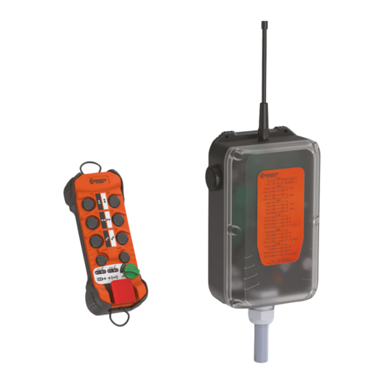
Page 9: Product Illustration
Product Illustration 4.1. Transmitter Front Face F5 double speed button Stop punch F3 double speed button ON / OFF switch • position 0 = OFF • position I = ON • position START = Validation F1 double speed button Amber LEDs C and D AUX1 AUX2 Push button AUX1 Push button AUX2 AUX1... -
Page 10: Receiver
4.2. Receiver Front Face RF Antenna Indicator LEDs Built-in Buzzer Transparent Cover with Wiring Label Cable Gland Numbered Wires Built-in White Lamp - 10 - MarK - 354840A... -
Page 11: Product Operation Principle
Product Operation Principle 5.1. General This set consists of a wireless command receiver and a transmitter. Radio communication between the two is two-way. The transmitter transmits the orders to the receiver, which decodes them, and activates its relay outputs depending on the setting. 5.2. Operating Modes MarK range products can operate in three distinct modes. Standard: a transmitter and a receiver that communicate over a radio channel „ AUX1 AUX2 AUX1 AUX2 Tandem: with two versions „ • a transmitter and two receivers that communicate over a single radio channel AUX1 AUX2 AUX1 AUX2 • two transmitters and two receivers that can communicate independently of each other. AUX1 AUX2 AUX1 AUX2 AUX1 AUX2 AUX1... -
Page 12: Start Up And Use
Start up and Use 6.1. Receiver Electrical Connection Instructions IMPORTANT: IF THE TRANSCEIVER IS POWERED DIRECTLY FROM THE DISTRIBUTION NETWORK, THE “IT” TYPE ELECTRICAL DISTRIBUTION DIAGRAM CANNOT BE USED FOR THE TRANSCEIVER POWER SUPPLY The electrical installation must be carried out by a trained and authorized professional. To avoid any risk of electrocution, never open the housing of the receiver module when it is powered on. -
Page 13: Rules Of Use And General Precautions
6.2. Rules of Use and General Precautions A radio-control system is considered as a control device. Its proper implementation must comply with resulting rules. The use of the system allows the operator to focus their attention on the work they are doing by choosing the place of observation limited only by safety requirements (e.g.: not parking under a suspended load). -
Page 14: Factory Defaults
6.3. Factory Defaults A fixed radio channel is automatically assigned „ Radio power is set to level 4 Fixed mode „ Standby is set to 4 minutes „ Buzzer is set to sound level 2, automatic pattern (the pattern depends on the channel) „ „ Without start-up protection sequence In automatic release mode and active sign-of-life mode „ Behavior of continuous AUX1 and AUX2 (Rsel_1 and Rsel_2 at 0) „ - 14 - MarK - 354840A... -
Page 15: Product Use
Product Use Getting Started Fault detected? List of faults Transmitter associated with receiver(s)? Primary or secondary pairing Configuration required? Operation for Controlling Equipment Settings Standard or Tandem Mode 7. Use of Products 7.1. Getting Started with Products 7.2. Pairing Primary Pairing (AUX1 + F1) off... -
Page 16: Getting Started With Products
7.1. Getting Started with Products 7.1.1. Powering On Power up the receiver, the amber Insert two AA batteries into the Unlock the transmitter by lifting the power LED lights up. back of the transmitter. punch stop. AUX1 AUX2 After three start-up attempts using the wrong code, the AUX1 AUX2 transmitter turns off. To restart, turn the AUX1 AUX2 ON / OFF switch to 0, then I. AUX1 AUX2 Start the transmitter by turning If LEDs A, B, C, and D flash at If the code is incorrect, the red the same time, the transmitter is LED lights up for 2 sec. -
Page 17: Power-On Self-Test (Default Off Button)
AUX1 AUX2 AUX1 AUX2 AUX1 AUX2 AUX1 AUX2 After successful initialization and if To start the radio link, turn the In the event of initialization „ products have been configured: failure or when a fault appears on ON / OFF switch to START • The radio LED is continuously on the transmitter, this is indicated by Or to go to product configuration, „ • The battery LED indicates the the various LEDs on the interface. activation 2 buttons and turn the charge level For the fault type, refer to... -
Page 18: Pairing
7.2. Pairing During a pairing, the transmitter and receiver exchange application settings and the radio channel over which they will communicate. The procedure for a primary or secondary pairing is similar, only the mode selection (step 1) and corresponding visual indication differ. Access to Configuration Mode Pairing Type Visual Indication (via transmitter interface) Primary AUX1 + F1 off Secondary AUX1 + F2 off Products must be ready for configuration (if the transmitter and receiver are not powered on and unlocked, perform the steps in Chapter 7.1). 7.2.1. Primary 7.2.2. Secondary Pairing Pairing AUX1 AUX2 AUX1... - Page 19 Steps 2-8 are the same for primary or secondary pairing. Different step depending on pairing type AUX1 AUX2 AUX1 AUX2 Primary Pairing: simultaneously When a receiver is found, the lights Release the ON / OFF switch to flash quickly to indicate it has been press AUX1 + F1. start pairing: LEDs A, B, C, and D light up one selected and is ready for pairing. Secondary Pairing: simultaneously press AUX1 + F2. after the other to indicate that Then, press and hold the 2 a receiver search is in progress.
- Page 20 abandon AUX1 AUX2 AUX1 AUX2 AUX1 AUX2 AUX1 AUX2 AUX1 AUX2 AUX1 AUX2 To start pairing, turn LEDs A, B, C, and D indicate If the receiver does not receive the the remaining time by turning ID code within 20 sec following the ON / OFF switch to START. off successively every 5 sec in switching the ON / OFF to START, Within 20 sec, press the F1 button the receiver aborts the pairing.
-
Page 21: Transmitter Ui
7.3. Transmitter UI 7.3.1. Safety Stop The transmitter is equipped with a stop punch-type button. This button must be unlocked before turning the ON / OFF switch to I, otherwise the transmitter cannot be used. To ensure that the stop punch works properly, the button must be manipulated once a year. 7.3.2. Transmitter LEDs The transmitter is equipped with the following visual indicators: Power indicator (“battery”) „ „ Radio indicator Two indicators, A and B, for the AUX 1 button „ Two indicators, C and D, for the AUX 2 button. „ 7.3.2.1. Battery Indicator (red LED) The red battery LED indicates the charge level. This level is visible after the transmitter is powered on (ON / OFF switch on I) or during operation of the radio control (radio transmission between the transmitter and the receiver). The table below shows the correspondence between LED status and the charge level of the transmitter: Transmitter Charge Status Red “Battery”... -
Page 22: Default Signaling
7.3.2.3. AUX Button Indicator Each AUX1 or AUX2 button can be assimilated, depending on its configuration: • to a 3-position or 2-position function switch • or a bistable control • or a maintained control Button configuration changes from one type to another each time the corresponding AUX button is pressed and is indicated by a pair of two LEDs: • LEDs A and B for the AUX1 button • LEDs C and D for the AUX2 button. When the transmitter is powered on, LEDs A, B, C, and D light up briefly during the initialization phase (2 sec), then resume the indication corresponding to the last positions saved before the last start performed previously. Button configurations can be changed by setting, refer to Chapter 8.3 for details. 7.3.3. Default Signaling When a fault appears on the transmitter, it is signaled via the various LEDs on its interface. Transmitter LED Status Description The battery LED and radio LED flash alternately Stop punch locked The battery LED and radio LED flash simultaneously Default buttons (F1 to F6, AUX1, AUX2) (remain pressed) -
Page 23: Receiver Indicators, Relays, And Outputs
7.4. Receiver Indicators, Relays, and Outputs 7.4.1. Receiver Visual Indicators The receiver has 3 internal LEDs, these are used to indicate the following statuses: Amber power LED: indicates that the receiver is ON „ Green radio LED: indicates that the receiver is communicating with a transmitter „ Red diagnostic LED: indicates default statuses. „ The receiver also has a light that is visible through the transparent cover. This allows you to see different operating phase statuses of the receiver: Description Light Status Safety Relay Position Receiver is free Light is OFF Open (“Tandem” mode) Receiver is communicating with Light is ON Closed a transmitter Receiver is being used by one of Light flashes once periodically Open the transmitters in “... -
Page 24: Safety Relay
7.4.4. Safety Relay The receiver is equipped with 2 safety relays. The two safety relays are active in operation as soon as the link is established between the transmitter and the receiver, as long as an active stop has not been received. 7.4.5. Function Relay Output Assignment Function relay outputs are assigned to function buttons as shown below: (K13) Function Buttons Relay Relay Relay Relay Relay Relay Relay Relay Relay ■ F1 SV F1 DV ■ ■ ■ F2 SV F2 DV ■ ■ ■ F3 SV F3 DV ■... -
Page 25: Output Interlock
7.4.6.2. Sel1 and Sel2 Relay - AUX2 Function RSel1 Relay Behavior (K11) RSel2 Relay Behavior (K12) Setting Switch 1 ON when AUX2 auxiliary button Maintained control Reverse of relay RSel1 (K11) is active Each time the AUX2 button is Bistable control pressed, the relay status changes Reverse of relay RSel1 (K11) (C/0) (OFF ↔ ON) 2 Position Selector Mode Pos 0: OFF Reverse of relay RSel1 (K11) (C/D) Pos 1: ON 2 Position Selector Mode Pos 0: ON Pos 0: OFF (C/D/C + D) -
Page 26: Operation In Standard Mode
7.5. Operation in Standard Mode For a transmitter to start a receiver, the products must be paired first. Each product has its own ID code, and each knows the code of its contact. These ID codes allow identification with the recipient of the message. Products must be ready (if the transmitter and receiver are not powered on and unlocked, perform the steps in Chapter 7.1). AUX1 AUX2 AUX1 AUX2 AUX1 AUX2 AUX1 AUX2 Turn the ON / OFF switch to Release the ON / OFF switch. Use the remote control to steer your equipment. -
Page 27: Operation In Tandem Mode
7.6. Operation in Tandem Mode This feature makes it possible to control two devices synchronously with a single transmitter and two receivers (one main and one secondary). This configuration can be symmetrical with another transmitter located within the same area. The AUX1 auxiliary button on the transmitter is used to select the steering type: Independent operation (standard mode one transmitter and only one of the two receivers) or operation of the two associated receivers at the same time: „ Tandem mode one transmitter (TxA) with two receivers (RxA and RxB) The AUX1 auxiliary button on the transmitter is used to select the steering type: Independent operation (standard mode one transmitter and only one of the two TxA-RxA or TxA-RxB receivers) or operation of the two associated receivers at the same time (TxA - RxA + RxB). AUX1 AUX2 AUX1 AUX2 Tandem mode two transmitters (TxA, TxB) and two receivers (RxA, RxB) „... -
Page 28: Startup In Tandem Mode
7.6.1. Startup in Tandem Mode In order to start in tandem mode, both receivers must be “free” That is, they are in safety mode and listening to the primary transmitter and neighboring transmitter. To start in Tandem mode, follow the three steps below: „ Switch on the products: follow the instructions described in Chapter 7.1. If starting in Tandem mode, check that the AUX1 button is set to selection A+B (LEDs A and B continuously ON). „ Otherwise press the AUX1 button as many times as necessary to reach this selection. It is possible to control one receiver at a time. In this case, the AUX1 button must be in position A or B before START. To start operating, turn the ON / OFF switch to START, then release it. „ When the receiver(s) start in tandem mode, the RAux relay on the receiver(s) is turned ON. This relay reflects the release status of the receiver. Status of the RAux relay in Tandem: • OFF: Free • ON: Busy. After the receiver has been switched on, it is in the free position, the RAux relay is open. -
Page 29: Auto Release
7.6.4. Auto Release After a safety shutdown or power failure, the receivers are automatically released. The receivers are again available and listening to the 2 transmitters. 7.6.5. Voluntary Release Depending on the settings it is possible to manually release the receivers, to: • release them for another use, or • keep them, but make them unavailable to the neighboring transmitter. When the receivers are not released, they keep the primary transmitter as the only contact. A receiver can be released before the transmitter is turned off (safety stop or turning the ON / OFF switch to OFF): Hold the AUX1 button for 4 seconds: the transmitter sends release frames to the receiver. The receiver „ acknowledges the release by switching off the respective RAux relay. After 4 seconds, the A, B, C, and D LEDs turn off. „ In some cases, release may not feasible (interference, receiver too far away), in this case the receiver remains busy. -
Page 30: Product Settings
Product Settings 8.1. Access to Settings All of the following settings must be configured after the primary pairing between the transmitter and the receiver. This operation must be done with the receiver powered on so that it can save the new settings. 8.1.1. Setting Entry In Setting mode, the behavior of the battery and radio LEDs is as follows: Description Transmitter Indicator Status A setting entry is active. The number of flashes of the battery LED/radio LED The red battery LED and the green radio LED flash pair indicates the setting being modified as long as the according to the Setting mode ON / OFF switch is maintained in the START position. After releasing the switch, the battery and radio LEDs are off. -
Page 31: Auxiliary Button Configuration (Aux1 + Aux2)
8.3. Auxiliary Button Configuration (AUX1 + AUX2) The transmitter’s auxiliary pushbuttons can be configured in several ways according to needs: They can be associated with the Relay’s function relays Raux, RSel1, and RSel2. The AUX1 and AUX2 can be configured as follows: Pushbutton with maintained control (AUX1 and AUX2) „ Bistable button (AUX1 and AUX2) „ Bridge selector button (Tandem AUX1) „ Relay selector button (AUX2). „ LEDs A and B indicate the current setting of the AUX1 button and LEDs C and D indicate the setting of the AUX2 button. The settings and corresponding light signals are listed in the table below: AUX1 button LED A LED B Maintained control (RAux relay) continuous Bistable control (RAux relay) flashing A/B selection A and B flashing alternately A/B/A + B selection ON sequence: A, B, A + B Continuous selection A A alone, then B flashing stealthily Tandem mode B alone, then A flashing stealthily Continuous selection B Continuous A + B selection... - Page 32 AUX1 AUX2 AUX1 AUX2 AUX1 AUX2 AUX1 AUX2 AUX1 AUX2 AUX2 AUX1 AUX2 AUX1 AUX2 Press and hold the AUX1 and Each time one of the AUX1 Release the ON / OFF switch to start the configuration. AUX2 buttons and turn the or AUX2 buttons is pressed, the lighting sequence of the ON / OFF switch to START: 2 corresponding LEDs indicates •...
-
Page 33: Sleep Mode Configuration (F1 + F3)
8.4. Sleep Mode Configuration (F1 + F3) The transmitter is put into standby mode if no function button has been pressed in the set time. The sleep time can be set from 1 to 99 minutes maximum and from 10 to 59 seconds. The factory setting is 4 minutes. Products must be ready for configuration (perform steps in Chapter 7.1). AUX1 AUX2 AUX1 AUX2 AUX1 AUX2 AUX1 AUX2 AUX1 AUX2 AUX1 AUX2 To disable sleep mode, press the Press and hold the F1 and F3 Release the ON / OFF switch: • LED D indicates the unit of time buttons and turn the ON / OFF AUX1 button: (minutes = off, seconds = on) •... -
Page 34: Radio Power Configuration (F1 + F4)
8.5. Radio Power Configuration (F1 + F4) By default, the transmitter and receiver modules analyze the quality of the signal received from both sides and adapt the power level according to the environment. However, it is possible to set the radio power of the products. Power is factory set to Fixed Level 4. There are 2 power modes: „ Auto LED D is continuously on and A, B, and C are off „ Fixed Manual; LED D is off and LED A indicates the value of the power set in the range 1 (min) to 4 (max) by successive flashing. Products must be ready for configuration (perform steps in Chapter 7.1). AUX1 AUX2 AUX1 AUX2 AUX2 AUX1 AUX2 AUX1 AUX2 AUX1 AUX2 Press and hold the F1 and F4 Release the ON / OFF switch to Press the AUX2 button to enable start the configuration. -
Page 35: Protection Sequence Configuration (Code With F1 - F6)
8.6. Protection Sequence Configuration (code with F1 – This setting protects the products with a code and prevents unauthorized use of the transmitter. The code represents a sequence obtained by a combination of the six F1 to F6 buttons. The button sequence can be variable in length, from a minimum of 2 buttons to a maximum of 6 buttons. It is possible to use the same button several times. Protection is not enabled in the factory setting. Products must be ready for configuration (if the transmitter and receiver are not powered on and unlocked, perform the steps in Chapter 7.1). AUX1 AUX2 AUX1 AUX2 AUX1 AUX2 AUX1 AUX2 Press and hold the F1 and F6 Release the ON / OFF switch to start the configuration. - Page 36 AUX1 AUX2 AUX1 AUX2 AUX1 AUX2 AUX1 AUX2 AUX1 AUX2 AUX1 AUX2 At the end of the sequence, Re-enter the code by pressing Release the ON / OFF switch: successively on the buttons confirm by turning the ON / OFF LEDs A and B are continuously on (chosen sequence): LED A turns switch to START. to indicate that the code must be re-entered to confirm it. off then on after each pressing of Note: If the sequence entered is incorrect (length), you are returned the F1 to F6 button.
- Page 37 When the sequence is incorrect, the red LED lights up for 2 sec and LEDs A, B, C and D flash. AUX1 AUX2 AUX1 AUX2 If the second code is different from the first code, resume Step 2. AUX1 AUX2 AUX1 AUX2 End of transmission: If the two codes entered are the same, the sequence is transmitted •...
-
Page 38: Rf Channel Configuration (F1 + F2)
8.7. RF Channel Configuration (F1 + F2) 8.7.1. Fixed Radio Channel Setting The radio channel of the transmitter and receiver can be set from 1-92 and the number of flashes of LEDs A and B indicate the radio channel number. Products must be ready for configuration (if the transmitter and receiver are not powered on and unlocked, perform the steps in Chapter 7.1). AUX1 AUX2 AUX1 AUX2 AUX1 AUX2 AUX2 AUX1 AUX2 AUX1 AUX2 Press and hold the F1 and F2 Release the ON / OFF switch Set the channel: to start the configuration. -
Page 39: Channel Auto Selection Setting (Aux2=Scanner)
8.7.2. Channel Auto Selection Setting (Aux2=Scanner) The AUX2 function scans the frequency band used in the area where products are installed and identifies channels not used in this area by other equipment. The scan must be started at the location of the transmitter and receiver and when there is the most “radio” activity in the area. Products must be ready for configuration (if the transmitter and receiver are not powered on and unlocked, perform the steps in Chapter 7.1). AUX1 AUX2 AUX1 AUX2 AUX2 AUX1 AUX2 AUX1 AUX2 AUX1 AUX2 LED A indicates the tenths and Press and hold the F1 and F2 Press the AUX2 button to start the LED B the units of the current procedure. During the scan, LEDs buttons and turn the ON / OFF... -
Page 40: Free Channel Startup Setting (F5)
8.7.3. Free Channel Startup Setting (F5) When the receiver is not communicating with the associated transmitter, it alternately listens to its current channel and the other channels of the frequency band. It then determines the channel that seems to be the best. Function F5 informs the transmitter at start-up to use the best available channel selected by the receiver. Products must be ready for configuration (if the transmitter and receiver are not powered on and unlocked, perform the steps in Chapter 7.1). AUX1 AUX2 AUX1 AUX2 AUX1 AUX2 AUX2 AUX1 AUX2 AUX1 AUX2 Press and hold the F1 and F2 Release the ON / OFF switch to Press the F5 button to enable start the configuration. -
Page 41: Frequency Agility Setting (F6)
8.7.4. Frequency Agility Setting (F6) Function F6 changes the channel automatically when it has been identified as busy, following a priority algorithm. Changing the radio channel is initiated by the receiver which transmits this information to the transmitter. Products must be ready for configuration (if the transmitter and receiver are not powered on and unlocked, perform the steps in Chapter 7.1). AUX1 AUX2 AUX1 AUX2 AUX1 AUX2 AUX2 AUX1 AUX2 AUX1 AUX2 Press and hold the F1 and F2 Release the ON / OFF switch to Press the F6 button to enable the start the configuration. -
Page 42: Receiver Buzzer Configuration (Aux2 + F1)
8.8. Receiver Buzzer Configuration (AUX2 + F1) This setting allows you to define different modes of operation of the buzzer signal according to needs and LEDs A,B,C, and D indicate the pattern and the sound level: „ Pattern Selection: Configurable from 1 to 99 ↔ LED A indicates tenths and LED B indicates the units. „ Automatic Pattern: This depends on the radio channel used ↔ indicated by LED D (automatic when the LED is on and manual when the LED is off). „ Sound Level: Configurable from 1 to 2 ↔ indicated by LED C (high if the LED is on and low if the LED is off). By default, products are delivered in automatic pattern mode and level 2. The buzzer is active according to a pattern depending on the setting or radio channel (automatic) of the receiver. Products must be ready for configuration (perform steps in Chapter 7.1). AUX1 AUX2 AUX1 AUX2 AUX2 AUX1 AUX2 AUX1 AUX2 AUX1 AUX2 Press and hold the AUX2 and F2 Release the ON / OFF button to To change the pattern: start configuration. LEDs indicate... - Page 43 AUX1 AUX2 AUX1 AUX2 AUX1 AUX2 AUX1 AUX2 AUX1 AUX2 AUX1 AUX2 Select the desired sound level Confirm the value by turning The AUX2 button enables using the AUX1 button. automatic mode. the ON / OFF switch to START. During transmission: • Battery and radio LEDs flash alternately •...
-
Page 44: Specific Tandem Mode Settings
Specific Tandem Mode Settings 9.1. Receiver Swapping A ↔ B (AUX1 + F5) This feature swaps the selection indicator of the AUX1 button. Swapping configuration is indicated by LEDs A and B: • The selection indicators of receivers A and B are not swapped if LED A is on and LED B is off • The selection indicators of receivers A and B are not swapped if LED A is off and LED B is on. Products must be ready for configuration (perform steps in Chapter 7.1). AUX1 AUX2 AUX1 AUX2 AUX2 AUX1 AUX2 AUX1 AUX2 x8 x4 AUX1 AUX2 Press and hold the AUX1 and F5 Release the ON / OFF switch: To switch from one mode to LEDs A and B indicate whether... -
Page 45: Release Function (Ungroup) (Aux1 + F3)
9.2. Release Function (Ungroup) (AUX1 + F3) This setting allows you to configure the release of one or more receivers that work with the transmitter. If automatic release mode is enabled, when the transmitter stops operating, the paired receiver(s) will be released and another transmitter can connect later. In the voluntary release mode, the operator must voluntarily release or not the receivers. Products are configured by default in automatic release mode. Release mode is indicated by the pair of A and B LEDs: • For automatic release, LED A is on and LED B is off • For voluntary manual release, LED A is off and LED B is on. Products must be ready for configuration (perform steps in Chapter 7.1). AUX1 AUX2 AUX1 AUX2 AUX2 AUX1 AUX2 AUX1 AUX2 x9 x9 AUX1 AUX2 Press and hold the AUX1 and F3 Release the ON / OFF switch: To switch from one mode to LEDs A and B indicate the active... -
Page 46: Sign Of Life Between Receivers (F1 + F5)
9.3. Sign of Life Between Receivers (F1 + F5) In Tandem mode a sign of life is exchanged between the two receivers. This function is only valid when the transmitter controls both receivers (A + B). The sign of determines if one of the receivers has released its safety relays or if radio communication between the two is broken. Products are configured at the factory in active life sign mode. Configuration of the sign of life mode is indicated by the pair of A and B LEDs: • Sign of life is enabled if LED A is on and LED B is off • Sign of life is disabled if LED A is off and LED B is on. If the sign of life disappears and one of the receivers has gone to safety, the second receiver will go to safety. If the sign of life disappears but the two receivers are still in operation (safety relay active), only the function output relay commands are disabled. Products must be ready for configuration (if the transmitter and receiver are not powered on and unlocked, perform the steps in Chapter 7.1). AUX1 AUX2 AUX1 AUX2 AUX2 AUX1 AUX2 AUX1... - Page 47 AUX1 AUX2 AUX1 AUX2 AUX1 AUX2 AUX1 AUX2 Confirm the selected status by End of transmission: • Receiver light turns off turning the ON / OFF switch to START. During transmission: • Transmitter shuts down • Battery and radio LEDs and restarts. flash alternately • Receiver light turns on. MarK - 354840A - 47 -...
-
Page 48: Installation Instructions
10. Installation Instructions 10.1. Transmitter Different button functions are identified by self-adhesive labels to be stuck on the transmitter box in the space provided for this purpose each button. Labels are delivered in sheets to be used according to the application. 10.2. Radio Receiver Position Preferably, the receiver should be mounted in a place that is protected from shock and weather. The antenna should be as far away as possible from the power cables (power supply, motor, drive, etc.), but remain in an area favorable to radio reception. It must be located within sight of the operator handling the equipment. There should be no metallic masses near it. The antenna will be located high above the operator handling the transmitter. There should be no metal between „ the operator and the antenna. „ The antenna is directed towards the working areas of the transmitter (downwards in the case of a hoist). The correct orientation of the antenna is shown in the figure below: „... -
Page 49: Mounting The Receiver
If the installation of the receiver does not allow the operator to see the antenna, it is advisable to offset the receiver antennas under the beams, and point them vertically towards the radio control area, as shown below: 10.3. Mounting the Receiver See Retrieve mechanical plan for attaching the housing. 10.4. Antennas 10.4.1. Antenna Type The receiver housing is equipped with a non-detachable antenna. However, it is possible to install a remote antenna. In this case, a BNC plug-in antenna kit must be purchased and installed (refer to Chapter 19.2 Accessories). MarK - 354840A - 49 -... -
Page 50: Locating Ordered Equipment
10.5. Locating Ordered Equipment If several devices are equipped with radio controls, working in the same vicinity (e.g. in a factory), each transmitter must carry clear information that tells the operator which equipment it controls. Similarly, the operator must be able to clearly identify the controls corresponding to the directions of movement of the equipment being steered. For this purpose, directional arrows are supplied with the receiver. Place the different arrows on the label on the equipment to be controlled, so that each arrow corresponds to the arrow on the associated transmitter button. The direction of action of the control buttons should, as far as possible, be consistent with the movement of the device being controlled. Symbols should be placed in such a way that there is a clear and unambiguous relationship between the action of the control buttons and the direction of movement. - 50 - MarK - 354840A... -
Page 51: Connection
10.6. Connection The receiver is equipped with an output cable for connecting the power supply and relay outputs. Below, the correspondence of the strand outputs and their assignments. Marker Diagram Strand Number Function Relay Fuse AC-1 Power input 40-230Vac Fus6 AC-2 Power input 40-230Vac Safety relay output 1 Fus5 Safety relay output 2 Fus5 Function ON output relay ON relay output AUX and selection Fus4 COM1 relay common Function relay output Raux Function relay output Aux 1 Rsel1 Function relay output Aux 2 Rsel2 Common 2 Fus2 COM2 Function relay output F1 F1.1 Function relay output F2... -
Page 52: Maintenance
11. Maintenance BEFORE PERFORMING ANY MAINTENANCE, TURN OFF THE POWER TO THE PRODUCT 11.1. Receiver Maintenance The housing can only be disassembled by trained personnel in a “controlled” environment. Parts can only be replaced with identical spare parts. Check the connection of the antenna; it must be clean and unoxidized. „ Check the quality of power supply and control output wiring. „ Correct operation of shutdown circuits, active. „ Condition of cover gasket, tightness of fastening screws. „ Use only non-aggressive soap-based cleaners. „ 11.2. Transmitter Maintenance The transmitter housing must not be opened. Regularly check the condition of the transmitter, paying particular attention to the batteries in the battery „... -
Page 53: Warranty
12. Warranty All our devices are guaranteed for two years from the day of shipment. Repairs, modifications or the replacement of a device during the warranty period shall not extend the warranty period. Restriction: The warranty does not cover defects resulting from: „ Transport „ Incorrect operation or failure to follow the connection diagrams during start up Lack of monitoring or maintenance, use not in accordance with the specifications in the technical manual and, „ in general, storage, operating or environmental conditions (atmospheric, chemical, electrical, mechanical or other influences) which are not suitable or not foreseen at the time of order The warranty cannot be exercised if modifications, dismantling or additions have been made by the customer without the written consent of our Company. The responsibility of JAY Electronique during the period of warranty is limited to any material or construction defect; this includes the repair in its workshops or the free replacement of parts recognized as defective according the expertise of its “technical services”. JAY Electronique cannot give right to any compensation for damages. In the event of a dispute concerning supply or payment, THE COMMERCIAL COURT OF GRENOBLE is the only competent authority, even in the event of Appeal or of plurality of defendants. MarK - 354840A - 53 -... -
Page 54: Technical Specifications
13. Technical Specifications 13.1. Receiver Mechanical Specifications and Environmental Resistance PA66 GF 30 (PC cover) Housing Material Black background and translucent/transparent cover Housing color Protection Index IP65 Mass 1.4kg (including cable) Overall Dimensions 310 (without antenna, with PES) x 150 (with buzzer) x 80mm 4x screws M3 – 229 x 90mm Fastening Possibility to add magnets with or without silent blocks -20°C to +55°C Operating Temperature -20°C to +70°C Storage Temperature 22-strands cable, section 0.75 mm², AWG 18 Connection (0.8mm² Kcmil) Length 1.5m PE M32 diam 17-25 Cable Entry Amber LED... -
Page 55: Dimensions
Electrical Specifications Power Supply 40Vac to 230Vac ± 10% - 50/60Hz Supply voltage (steady state) Fuse 0.5 A Protection <15W Consumption Safety relay outputs Number of outputs (2 relays in series) AgNi + Au Contacts Guided contact relays Contact Type 250Vac @ 5A max (at max operating temperature) Break Capacity 12Vdc @ 50mA min 2000VA Max Power at cos ø = 1 Switching Lifespan at 230VAC, 6A, cos ø... -
Page 56: Transmitter
13.2. Transmitter Mechanical Specifications and Environmental Resistance PA66 GF 30 Housing Material Orange RAL2010 Housing color Protection Index IP65 300g max Mass Overall Dimensions 180 x 70 x 45mm -20°C to +50°C Operating Temperature -30°C to +70°C Storage Temperature Transport 2 strap anchor points Foam, protective cover Protection Breathable membrane (internal anti-condensation) Yes Electrical Specifications Battery (US) Power Supply Number of function buttons... -
Page 57: Radio
13.3. Radio Radioelectrical Specifications (US) 433-440MHz Transmission Frequency Number of Channels 75kHz Space Between Channels Receiver Sensitivity -100dBm Transmission Power Modulation Hamming 4 distance with encryption against Frame external attacks Medium Range* 50-100m in industrial setting* 400m in open space Antenna Output Impedance 50 Ohms Response Time at Startup 500ms Command Response Time 300ms... -
Page 58: Fcc (Federal Communications Commission) Regulations
14. FCC (Federal Communications Commission) Regulations Products comply with the requirements of the Federal Communications Commission FCC Part 15, Subpart C, Section 15.231 (b)(2) Periodic operation in the band 40.66-40.70 MHz and above 70 MHz. 14.1. FCC (Federal Communications Commission) Regulations Any changes or modifications to this equipment not expressly approved by JAY Electronique could result in cause „ harmful interference and void the FCC authorization to operate this equipment. This equipment has been tested and found to comply with the limits for a Class A digital device, pursuant to the FCC Part 15. These limits are designed to provide reasonable protection against harmful interference when the equipment is operated in a commercial environment. This equipment generates, uses, and can radiate radio frequency energy and, if not installed and used in accordance with the instruction manual, may cause harmful interference to radio communications. - Page 59 14. Réglementation FCC (Commission fédéral des communications) Les produits sont conformes avec les exigences de la commission fédéral des communications FCC part 15, Subpart C, Section 15.231 (b)(2) Periodic operation in the band 40.66-40.70 MHz and above 70 MHz. 14.1. Réglementation FCC (Commission fédéral des communications) Toutes modifications apportées à cet équipement non expressément approuvées par JAY Electronique peuvent „ causer des interférences nuisibles et annuler l'autorisation FCC d'utiliser cet équipement. Cet équipement a été testé et déclaré conforme aux limites d’un appareil numérique de classe A, conformément à la FCC part 15. Ces limites sont conçues pour fournir une protection raisonnable contre les interférences nuisibles lorsque l’équipement est utilisé dans un environnement commercial. Cet équipement génère, utilise et peut émettre de l’énergie radiofréquence et, s’il n’est pas installé et utilisé...
-
Page 60: Standards And Environmental Specification
15. Standards and environmental specification According to the standard: Safety requirements for electrical equipment for measurement, control, and laboratory use; • IEC 61010-1:2010/AMD1 :2016 • UL 61010-1:2012/R :2019-07 • CSA C22.2 No. 61010-1:2012/A1 :2018-11 Degrees of protection provided by enclosures (IP code): • IEC 60529:1989/A1:1999 16. Recycling and Waste Management When this device is worn, it should not be disposed of in any kind of dumping ground. It can be taken to the specific collection centers, differentiated by local administrations, or to the distributors who take care of them. The sorting of electronic waste avoids possible negative consequences on the environment, derived from an inappropriate elimination and allows the processing and recycling of its materials, which favors important savings in terms of energy and resources. 17. Manufacturer Information Manufacturer and Factory: Jay électronique ZAC la Bâtie, rue Champrond F38334 SAINT ISMIER Cedex Tel: + 33 (0)4 76 41 44 00 ww.jay-electronique.com 18. -
Page 61: Appendix
19. Appendix 19.1. Radio Frequency Table channel 1 433.1MHz channel 32 435.425MHz channel 63 437.75MHz channel 2 433.175MHz channel 33 435.5MHz channel 64 437.825MHz channel 3 433.25MHz channel 34 435.575MHz channel 65 437.9MHz channel 4 433.325MHz channel 35 435.65MHz channel 66 437.975MHz channel 5 433.4MHz channel 36 435.725MHz channel 67 438.05MHz channel 6 433.475MHz channel 37 435.8MHz channel 68 438.125MHz channel 7 433.55MHz channel 38 435.875MHz channel 69 438.2MHz channel 8 433.625MHz channel 39 435.95MHz channel 70 438.275MHz channel 9 433.7MHz channel 40 436.025MHz channel 71 438.35MHz channel 10 433.775MHz channel 41 436.1MHz channel 72 438.425MHz channel 11 433.85MHz channel 42 436.175MHz channel 73 438.5MHz channel 12 433.925MHz channel 43 436.25MHz channel 74 438.575MHz channel 13 434MHz... -
Page 62: Accessories
19.2. Accessories 19.2.1. US Version OWE20 Neck strap included with each transmitter PWM111 Hand strap UDWR38 Receiver magnetic mounting kit UWE102 Shoulder strap PWM113 Transmitter magnetic mount UWE106 Transmitter belt clip UWE320 Transmitter protective cover UWE321 Transmitter belt carrying sleeve 19.2.2 External antenna option - 62 - MarK - 354840A... - Page 64 ZAC la Bâtie, rue Champrond F38334 SAINT ISMIER Cedex Tel: +33 (0)4 76 41 44 00 www.jay-electronique.com...
Need help?
Do you have a question about the MarK Series and is the answer not in the manual?
Questions and answers