Sign In
Upload
Download
Table of Contents
Contents
Add to my manuals
Delete from my manuals
Share
URL of this page:
HTML Link:
Bookmark this page
Add
Manual will be automatically added to "My Manuals"
Print this page
×
Bookmark added
×
Added to my manuals
Manuals
Brands
Lewmar Manuals
Outboard Motor
TT 140
Owners installation, operation & basic servicing manual
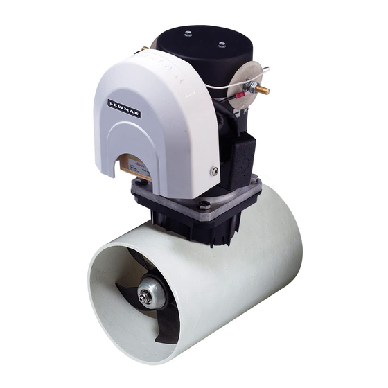
Lewmar TT 140 Owners Installation, Operation & Basic Servicing Manual
Electric/hydraulic tt thruster
Hide thumbs
1
2
Table Of Contents
3
4
5
6
7
8
9
10
11
12
13
14
15
16
17
18
19
20
21
22
23
24
25
26
27
28
page
of
28
Go
/
28
Contents
Table of Contents
Bookmarks
Table of Contents
Table of Contents
Introduction
Product Support
Important Information about this Manual
Approvals
Safety Notices
General
Thruster Supply
Fitting
Electrical
Installation
Choosing Location
Preparing the Hole for the Tube
Preparing for Fi Tting the Thruster
Installing Hub Unit and Saddle Models 140TT & 185TT
Gearbox Position - 185TT Only
Propeller Assembly - All Models
Installing Hub Unit and Saddle Models 250TT & 300TT
Electric Motor Unit Support
Installing Electric Motor Unit Model 140TT & 185TT
Installing Electric Motor Unit Model 250TT & 300TT
Installing Hydraulic Motor Unit Model 185TTH to 300TTH
Final Checks - All Models
Electrical Wiring Installation
Typical Electrical Layout Model 140TT 2.0 Kw Only
Typical Electrical Layout Models 140TT 2.2 Kw and 185TT
Typical Electrical Layout Models 250TT & 300TT
Electric Motor Terminal Connections
Battery Cable Connections
Correct Cable Sizes
Electrolytic Test
Installing Control Panel - All Models
Final Checks
Operating Your Thruster
140TT 2.0 Kw
140TT 2.2 Kw to 300TT 15.0 Kw Operation and Safety Features
Servicing Your Thruster
Changing Drive Pin 140TT or 185TT
Weight & Specifi Cations
Electric
Hydraulic
Parts List
Model 140TT 2.0 Kw 12 V
Model 140TT 2.2 Kw 12 V
Model 185TT/H 3.0 to 6.0 Kw 12 & 24 V
Model 250TT/H 8.0 Kw 24 V
Model 300TT/H 10.8 to 15.0 Kw
Accessories
Dimensions
Electric
Hydraulic
Fault Fi Nding
Cutting Templates
Lewmar Limited Warranty
Advertisement
Quick Links
1
Electrical
2
Electrical Wiring Installation
3
Model 185Tt/H 3.0 to 6.0 Kw 12 & 24 V
Download this manual
500100 Issue 3
T1873 Lewmar USA4 Thruster 140 to 00 I
Electric/Hydraulic
T T Thruster 140-300
Owner's Installation, Operation &
Basic Servicing Manual
www.lewmar.com
Electric/Hydraulic TT Thruster 140 - 300
GB
GB
1
Table of
Contents
Previous
Page
Next
Page
1
2
3
4
5
Advertisement
Table of Contents
Need help?
Do you have a question about the TT 140 and is the answer not in the manual?
Ask a question
Questions and answers
Related Manuals for Lewmar TT 140
Outboard Motor Lewmar TT Series Owners Installation, Operation & Servicing Manual
Electric thruster (17 pages)
Outboard Motor Lewmar TT 250 Owners Installation, Operation & Basic Servicing Manual
Electric/hydraulic tt thruster (28 pages)
Outboard Motor Lewmar 140TT Owners Installation, Operation & Basic Servicing Manual
Electric/hydraulic stern thruster (9 pages)
Outboard Motor Lewmar 250 VRTT Series Manual
(32 pages)
Outboard Motor Lewmar 125 VRTT Owners Installation, Operation & Servicing Manual
Pontoon thruster (25 pages)
This manual is also suitable for:
Tt 185
Tt 250
Tt 300
Table of Contents
Save PDF
Print
Rename the bookmark
Delete bookmark?
Delete from my manuals?
Login
Sign In
OR
Sign in with Facebook
Sign in with Google
Upload manual
Upload from disk
Upload from URL


Need help?
Do you have a question about the TT 140 and is the answer not in the manual?
Questions and answers