Table of Contents
Advertisement
Quick Links
Advertisement
Table of Contents

Subscribe to Our Youtube Channel
Related Manuals for Lewmar 250 VRTT Series


Summary of Contents for Lewmar 250 VRTT Series
- Page 1 250 & 300 VRTT Revision D 07/03/07...
-
Page 2: Table Of Contents
INDEX Page 1. INTRODUCTION 2. INSTALLATION 2.1 Fitting the Thruster 2.1.1 Placement 2.1.2 Lifting 2.1.3 Hull fitting 2.1.4 Raise/Lower setting 2.1.5 Painting 2.2 Thruster Main Drive Installation 2.2.1 Hydraulic 2.2.2 Electric 2.3 Thruster Electrical Control Installation 3. OPERATION 4. MAINTENANCE 4.1 Periodic Maintenance 4.2 Cathodic Protection 4.3 Manual Operation... -
Page 3: Introduction
INTRODUCTION The Lewmar VRTT Thruster has been designed to give excellent service and a long life providing that it is installed and serviced properly. This manual provides the information required for the correct installation of your new Lewmar VRTT Thruster This manual applies to the following thruster models: 59127002 –... -
Page 4: Installation
INSTALLATION These are guidelines only it is recommended that a professional marine engineer perform the Thruster installation. 2.1 Fitting the Thruster The VRTT Thruster is supplied with the leg raised for ease of installation. Correct installation of the Thruster, associated equipment and the watertight integrity of the vessel is the responsibility of the installer. -
Page 5: Lifting
2.1.2 Lifting the unit The Thruster is heavy so when lifting the Thruster unit from its packing case, ensure that adequate lifting strops are used. The Thruster should not be lifted by its lead screw assembly or propeller shroud. Extra caution should be used to avoid damaging these parts, the micro switches and control box. - Page 6 the box at high pressure potentially damaging the gasket/seal and to eliminate load being applied to the Thruster leg when the vessel is pounding at sea. A sealing gasket is recommended between the closing plate and hull register. This should be of a resilient material that will not cause sticking of the closing plate and undue load on the raise/lower mechanism.
-
Page 7: Raise/Lower Setting
2.1.4 Raise/Lower Setting The limit switches are factory set at a pre-determined safe setting and will require adjustment during installation. The Limits switches are activated by the adjustable stops. The stops can be adjusted by loosening the lock nuts either side of the stop with a 13mm spanner, adjusting and re-tightening sufficient to stay in position but not crush the plastic stop. -
Page 8: Painting
2.1.5 Painting/protection The Thruster base plate is supplied bare aluminium ready for anti-fouling. There are 6 anodes fitted to the under water area, 2 on the propeller shafts and 4 mounted directly on to the base plate, these must not be painted or anti-fouled as this is will prevent them from protecting the unit. -
Page 9: Thruster Main Drive Installation
Hydraulic units must be checked for stray current along the supply hoses. If found the motor must be fitted with correctly rated and sized insulated hoses. Lewmar cannot accept responsibility for corrosion caused by stray voltage. When first operating the Thruster, pulse the controller to charge (fill) the... -
Page 10: Electric
48Vdc supply to the main drive thruster motor, but a separate 24Vdc supply to the Raise/Lower control system. N.B. A Lewmar TT P/S Battery Switch box is supplied with this thruster to enable the installer to double a 24Vdc supply to 48Vdc to the thruster using additional batteries. - Page 11 48Vdc: Refer to chart below for recommended Cable size based on maximum voltage drop, depending on run and fuse required. Lewmar also supply a fuse holder 589013. Maximum total cable run Battery to Thruster and back Cable CSA mm Fuse Part No.
- Page 12 1. Correct installation. Supplied cable boots are used and no bare wires exposed. 2. Live wire exposed! Correct the cable installation to match illustration 1 3. Terminal or motor is damaged. Contact Lewmar Ltd 4. Crimp inverted and is touching motor! Correct the cable installation to match illustration 1...
- Page 13 To prevent electrolytic corrosion or faults, the thruster motor body and assembly must remain isolated from any power supply or grounds. The installer can check for this using a multimeter in the following ways: Test 1 With the negative not connected and the positive cable connected but with the battery switch off or fuse removed.
- Page 14 Test 2 With the battery applied: Use a voltmeter to test the voltage between the –ve stud and the thruster motor body. If the supply voltage is measured, disconnect power immediately and inspect the assembly for faulty installation or damage. IMPORTANT: Do not run the thruster out of the water, even for a few seconds, the motor will overspeed by 300% causing damage to the seals etc.
-
Page 15: Thruster Electrical Control Installation
2.3 Thruster Electrical Control Installation The 250/300 VRTT thruster is supplied with a Raise/Lower control box pre- wired to the thruster limit switches, raise/lower motor and main drive motor control (VRTTE only). The operation and factory fitting of the control box and raise/lower assembly is tested prior to shipment. - Page 16 VRTTE only: The control connections available for customer installation are as follows 1 – Power supply to raise/lower control switches & lamps. 2 – Switched (latched) power in to box to enable raise/lower control. 3 – Switched (momentary) power signal in to initiate a thruster raise operation. 4 –...
- Page 17 A user interface control panel for controlling the raise/lower mechanism and main thruster drive has been designed by Lewmar Ltd specifically for this thruster and may be ordered separately, part number 58400612: Loom 1 Loom 2 The panel dimensions are 100mm X 85mm. And is rated IP67 above the panel when installed correctly with the use of a suitable gasket or sealing compound.
- Page 18 Loom 1 of the VRTT control panel is interfaced with the VRTTE main electric drive motor ‘Black Box’ control unit using standard Lewmar TT thruster control loom connecting cables sourced separately: Cable Length Part Number 589021 589016 589017 589018 589019...
- Page 19 VRTTE Main Drive Control & Power Connections 24Vdc:...
- Page 20 48Vdc:...
- Page 21 VRTTH Main thruster drive control: The switched joystick on the VRTT panel can also be used for valve control on a VRTTH installation. Note, the connector supplied on loom 1 will have to be discarded. This is a basic wiring diagram to aid the installer in the basic control of the hydraulic thruster.
- Page 22 In most cases the VRTTH is integrated into a hydraulic system where there are existing hydraulic controls. If this thruster is part of a complete Lewmar hydraulic/electric system, please refer to the main system manual for piping and wiring information.
-
Page 23: Operation
OPERATION This section details the operation of the thruster based on the installation of the VRTT panel, if this panel was not used the operation may differ. The panel consists of three pushbuttons with integral indicators: Thruster- Raise(momentary), Thruster-Lower(momentary) and System On/Off(latching) Also there will be either a switched joystick or pushbuttons for control of actual thrusting. - Page 24 The VRTT control Box features a Circuit breaker that is sized such that any obstructions to the movement of the thruster to retract or deploy will cause the circuit breaker to trip which will remove power from the VRTT control system. The circuit breaker can be reset by pushing the trip button back in, But what ever caused the obstruction must be removed before attempting to switch the system on again.
-
Page 25: Maintenance
Note The Thruster hub is a sealed unit and does not require general maintenance, if a problem is found, please contact your nearest Lewmar representative. Hydraulic system maintenance should be carried out in accordance with the manufacturers instructions. Failure to do this will result in the reduced life of... -
Page 26: Cathodic Protection
4.2 Cathodic Protection System When the boat is first commissioned it is important that the Anodes are checked frequently at one-month intervals. Check for signs of excessive corrosion. If the Anodes have corroded significantly, renew immediately. If the Anodes/unit shows signs of corrosion shortly after commissioning then it is important that the vessel electrical system is checked for earth leaks, or other electrical faults that are possibly accelerating the corrosion process. -
Page 27: Manual Operation
4.3 Manual Raise & Lower of Thruster If the Thruster cannot be raise or lowered using Electrical power, it is possible to raise or lower the unit mechanically. WARNING When lowering manually remove or isolate power to prevent injury. 1) Remove 6mm Cross Bolt from the drive assembly of the raise/lower motor using a 8mm spanner and 3mm hex key. -
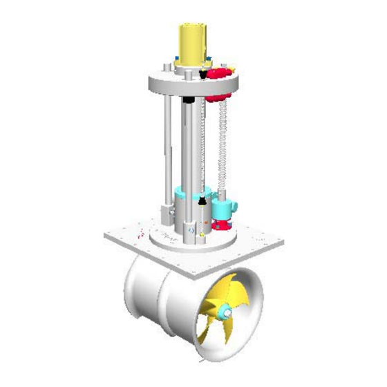
Page 28: Drawings
Note: Version Shown is Hydraulic, Dim ‘A’ Accounts for Both Electric & Hydraulic... - Page 30 D SEVERANCE CLAUSE Lewmar garantiert für einen Zeitraum von drei Jahren ab Kaufdatum – den Lewmar warrants its products in normal usage to be free of defects in materials der vom Käufer bezweckten Nutzung, des Gebrauchs, der Art, der and workmanship for a period of three years from date of purchase by the normalen Gebrauch der Produkte vorausgesetzt -, daß...
- Page 31 Lewmar. despacho y no incluyen el IVA que se cargará según sea apropiado.
- Page 32 Bristfälligheter, förlust eller skada till följd av förhållanden som överskrider produktens prestandaspecifikation. Offerter iv Produkt som är föremål för anspråk enligt garantin måste returernas till Lewmar Alla offerter avges med förbehåll för godtagande under en period om 30 dagar för undersökning såvida ej annat förfaringssätt skriftligen har medgivits av från och med offertdatum.
Need help?
Do you have a question about the 250 VRTT Series and is the answer not in the manual?
Questions and answers