
Related Manuals for HLF 37-4700 G1F


Summary of Contents for HLF 37-4700 G1F
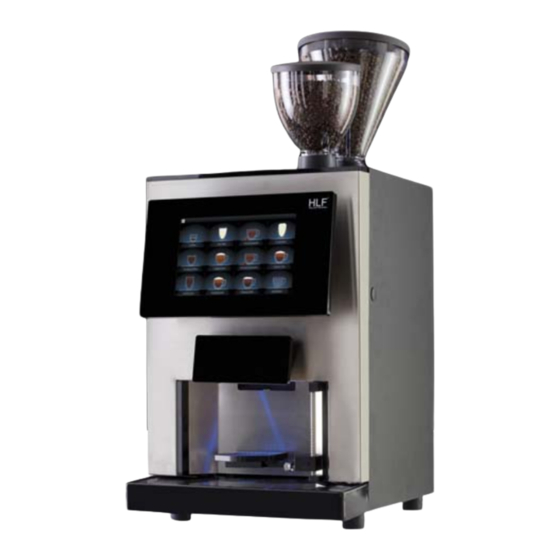
- Page 1 SERVICE MANUAL HLF 37-4700 G1/2/F ENGLISH HLF Italian Design S.M. HLF 37-4700 G1-G2-F Eng V1-2017...
- Page 2 HLF company. The content may not be disclosed or made available to any third party without the express consent of the HLF company. These Operating Instructions must be read and applied by anyone performing work with or on the equipment described.
-
Page 3: Table Of Contents
6.1.4 Removing the right side panel ............6-5 6.1.5 Removing the door cover ..............6-6 Removing modules .....................8-1 Removing the grinder module ...............8-1 S.M. HLF 37-4700 G1-G2-F Eng V1-2017 HLF Italian Design... - Page 4 8.12.1 Removing the coffee group gearmotor ..........8-41 8.13 Removing the drip catcher module ............. 8-42 8.13.1 Removing the drip catcher module gearmotor ......... 8-45 HLF Italian Design S.M. HLF 37-4700 G1-G2-F Eng V1-2017...
- Page 5 14.10 E25-CHECK FILTER ................ 14-10 14.11 E39-COFFEE GROUP POSITIONING ..........14-11 14.12 E46-FRIDGE PROBE OVER TEMPERATURE ........ 14-11 14.13 E47-FRIDGE PROBE DISCONNECTED.......... 14-11 S.M. HLF 37-4700 G1-G2-F Eng V1-2017 HLF Italian Design...
- Page 6 E92-FLASH WRITE ERROR TRIAC BOARD 1 ........ 14-22 14.36 E100-FLASH WRITE ERROR OUTPUT BOARD 1 / E101-FLASH WRITE ERROR OUTPUT BOARD 2 ..............14-22 14.37 E102-EEPROM WRITE ERROR MOTHERBOARD ......14-22 HLF Italian Design S.M. HLF 37-4700 G1-G2-F Eng V1-2017...
- Page 7 14.58 E143-DRIP CATCHER MOVEMENT TIMEOUT ....... 14-36 14.59 E170-DRIP CATCHER DISCONNECTED ........14-36 Electronic boards description ................. 15-1 15.1 Mother board ....................15-2 S.M. HLF 37-4700 G1-G2-F Eng V1-2017 HLF Italian Design...
- Page 8 Power stabilizer ..................15-7 Planning diagram ....................16-1 Electric diagram ....................17-1 Hydraulic circuit ....................18-1 Spare part list ....................19-1 HLF Italian Design S.M. HLF 37-4700 G1-G2-F Eng V1-2017...
-
Page 9: User Manual
USER MANUAL 1 User Manual S.M. HLF 37-4700 G1-G2-F Eng V1-2017 HLF Italian Design... -
Page 11: Exploded Views
EXPLODED VIEWS 2 Exploded views 2.1 General exploded view S.M. HLF 37-4700 G1-G2-F Eng V1-2017 HLF Italian Design... - Page 12 Mixing bowl Milk outlet valve cover Coffee group aspirator fan 10. Coffee group 11. Drip catcher 12. Drip tray switch cover 13. Grounds drawer 14. Cup holder grid 15. Drip tray HLF Italian Design S.M. HLF 37-4700 G1-G2-F Eng V1-2017...
- Page 13 EXPLODED VIEWS Electronic boards module Coffee group gearmotor module Touch screen power supplier Powder gearmotors module Boiler module Power supply module Pump module Fan module S.M. HLF 37-4700 G1-G2-F Eng V1-2017 HLF Italian Design...
-
Page 14: Pump Module Exploded View
EXPLODED VIEWS 2.2 Pump module exploded view Air-break Water pump Cold water inlet fitting Main water inlet valve Milk module flow meter Pump restrictor Flow meter HLF Italian Design S.M. HLF 37-4700 G1-G2-F Eng V1-2017... -
Page 15: Boiler Module Exploded View
Mixer 3 valve (2 ways) [Only for 4700 G1-G2 (no fresh milk)] Mixer 1 valve (2 ways) 10. Mixer 2 valve (2 ways) 11. Hot water valve (2 ways) 12. Discharge valve (2 ways) S.M. HLF 37-4700 G1-G2-F Eng V1-2017 HLF Italian Design... -
Page 16: Milk Module Exploded View
Hot milk outlet valve (2 ways) Hot milk pump Cold milk pump 10. Hot milk air regulator 11. Cold milk air regulator 12. Water / hot milk exchange valve (3 ways) HLF Italian Design S.M. HLF 37-4700 G1-G2-F Eng V1-2017... -
Page 17: Power Supply Module Exploded View
EXPLODED VIEWS 2.5 Power supply module exploded view Water level board Output board 2 Main switch Power cable socket Output board 1 Net filter Milk fridge connector S.M. HLF 37-4700 G1-G2-F Eng V1-2017 HLF Italian Design... -
Page 18: Electronic Boards Module Exploded View
EXPLODED VIEWS 2.6 Electronic boards module exploded view Power stabilizer Mother board Triac board HLF Italian Design S.M. HLF 37-4700 G1-G2-F Eng V1-2017... -
Page 19: Powder Gearmotors Module Exploded View
2.7 Powder gearmotors module exploded view Powder gearmotor for soluble 1 Powder gearmotor for soluble 2 Powder gearmotor for soluble 3 Powder gearmotor for soluble 4 [Only for 4700 G1-G2 (no fresh milk)] S.M. HLF 37-4700 G1-G2-F Eng V1-2017 HLF Italian Design... -
Page 20: Coffee Group Gearmotor Module Exploded View
EXPLODED VIEWS 2.8 Coffee group gearmotor module exploded view Coffee group gearmotor Gearmotor shaft HLF Italian Design 2-10 S.M. HLF 37-4700 G1-G2-F Eng V1-2017... - Page 21 S.M. HLF 37-4700 G1-G2-F Eng V1-2017 HLF Italian Design...
-
Page 23: Ordinary Maintenance
It consists in all those operations to do after an estimated period, according to the factory recommendations. 4.1 Removing the coffee group Step Action Illustration Remove the drip tray and the grounds drawer. Disconnect the silicon tube and unlock the blue coffee group lock lever. S.M. HLF 37-4700 G1-G2-F Eng V1-2017 HLF Italian Design... - Page 24 ORDINARY MAINTENANCE Removing the coffee group Step Action Illustration Turn the coffee group lever downward and let the coffee group to go down. HLF Italian Design S.M. HLF 37-4700 G1-G2-F Eng V1-2017...
- Page 25 Removing the coffee group ORDINARY MAINTENANCE Step Action Illustration Pull the coffee group toward you and take it off the machine. S.M. HLF 37-4700 G1-G2-F Eng V1-2017 HLF Italian Design...
- Page 26 HLF Italian Design S.M. HLF 37-4700 G1-G2-F Eng V1-2017...
-
Page 27: Sealings And Filters Replacement (10000 Cycles Kit Installation)
36,10 X 3,53 mm Red silicon O-ring 2015 3,68 X 1,78 mm Red silicon O-ring 2037 9,25 X 1,78 mm Silicon lip gasket Red silicon O-ring 3150 37,7 X 2,62 mm S.M. HLF 37-4700 G1-G2-F Eng V1-2017 HLF Italian Design... - Page 28 ORDINARY MAINTENANCE Sealings and filters replacement Step Action Illustration Remove the 6 screws that hold the coffee group upper base. HLF Italian Design S.M. HLF 37-4700 G1-G2-F Eng V1-2017...
- Page 29 Sealings and filters replacement ORDINARY MAINTENANCE Step Action Illustration Take off the coffee group upper base. S.M. HLF 37-4700 G1-G2-F Eng V1-2017 HLF Italian Design...
- Page 30 ORDINARY MAINTENANCE Sealings and filters replacement Step Action Illustration Unscrew the coffee group inlet nozzle and replace the O-Rings C and H. Put it back. HLF Italian Design S.M. HLF 37-4700 G1-G2-F Eng V1-2017...
- Page 31 Sealings and filters replacement ORDINARY MAINTENANCE Step Action Illustration Remove the 2 screws that hold the coffee group top piston and remove it. Replace: O-Ring F O-Ring G Filter B Put everything back. S.M. HLF 37-4700 G1-G2-F Eng V1-2017 HLF Italian Design...
- Page 32 ORDINARY MAINTENANCE Sealings and filters replacement Step Action Illustration Remove the 6 screws that hold the coffee group lower base and the cover. HLF Italian Design 4-10 S.M. HLF 37-4700 G1-G2-F Eng V1-2017...
- Page 33 Sealings and filters replacement ORDINARY MAINTENANCE Step Action Illustration Take off the coffee group lower base. Take off the coffee group chamber. S.M. HLF 37-4700 G1-G2-F Eng V1-2017 4-11 HLF Italian Design...
- Page 34 ORDINARY MAINTENANCE Sealings and filters replacement Step Action Illustration Unscrew the coffee group chamber inlet nozzle and replace O-Rings C and H. Put it back. HLF Italian Design 4-12 S.M. HLF 37-4700 G1-G2-F Eng V1-2017...
- Page 35 Sealings and filters replacement ORDINARY MAINTENANCE Step Action Illustration Remove the screw that holds the coffee group bottom head to the coffee group shaft. S.M. HLF 37-4700 G1-G2-F Eng V1-2017 4-13 HLF Italian Design...
- Page 36 Remove the coffee group shaft. Replace: - filter B - gasket D - O-Ring E Insert the coffee group shaft into the coffee group chamber and screw back the bottom head. HLF Italian Design 4-14 S.M. HLF 37-4700 G1-G2-F Eng V1-2017...
- Page 37 Step Action Illustration Remove the 2 screws that hold the coffee group brush holder and replace the silicon brush “A”. Put back the coffee group brush holder. Put everything back. S.M. HLF 37-4700 G1-G2-F Eng V1-2017 4-15 HLF Italian Design...
- Page 38 Pull out the mixing blade. Turn right the mixing bowl holder till the end and pull it out. Replace the lip gasket I and the silicon O-ring J. HLF Italian Design 4-16 S.M. HLF 37-4700 G1-G2-F Eng V1-2017...
-
Page 39: Grinder Blades Replacement
6.1.2 Removing the top lid. Step Action Illustration Close the beans hopper stoppers. Lift up the shaft that blocks the black supports. Turn counterclockwise the black supports. S.M. HLF 37-4700 G1-G2-F Eng V1-2017 4-17 HLF Italian Design... - Page 40 ORDINARY MAINTENANCE Grinder blades replacement Step Action Illustration Remove the beans hoppers and clean all the remaining beans using a vacuum. HLF Italian Design 4-18 S.M. HLF 37-4700 G1-G2-F Eng V1-2017...
- Page 41 Grinder blades replacement ORDINARY MAINTENANCE Step Action Illustration Unscrew the top lid holding knob. Lift the back part of the top lid. Push it to the front to remove S.M. HLF 37-4700 G1-G2-F Eng V1-2017 4-19 HLF Italian Design...
- Page 42 Note: before taking off the grinder 1 is necessary to remove the grinder 2 adjuster from the basement. Unscrew the 3 knobs that hold the grinder plate, lift it up and unplug the connector. HLF Italian Design 4-20 S.M. HLF 37-4700 G1-G2-F Eng V1-2017...
- Page 43 Put a new grinder head. Remove the bottom blade holding nut and replace the bottom blade. ATTENTION: the nut has to be turn clockwise to unscrew. S.M. HLF 37-4700 G1-G2-F Eng V1-2017 4-21 HLF Italian Design...
- Page 45 S.M. HLF 37-4700 G1-G2-F Eng V1-2017 HLF Italian Design...
-
Page 47: Extraordinary Maintenance
This paragraph shows hot to remove the various machine metal plates to reach the components. 6.1.1 Removing the back panel Step Action Illustration Unscrew the 4 screws that hold the back panel. S.M. HLF 37-4700 G1-G2-F Eng V1-2017 HLF Italian Design... - Page 48 EXTRAORDINARY MAINTENANCE Removing metal plates Step Action Illustration Lift the back panel and than pull it toward you. HLF Italian Design S.M. HLF 37-4700 G1-G2-F Eng V1-2017...
-
Page 49: Removing The Top Lid
Removing metal plates EXTRAORDINARY MAINTENANCE 6.1.2 Removing the top lid Step Action Illustration Pull the top lid toward you. S.M. HLF 37-4700 G1-G2-F Eng V1-2017 HLF Italian Design... -
Page 50: Removing The Left Side Panel
Remove the 3 screws that hold the left side panel to the back of the machine. Remove the 3 screws that hold the left side panel to the internal side of the machine. HLF Italian Design S.M. HLF 37-4700 G1-G2-F Eng V1-2017... -
Page 51: Removing The Right Side Panel
Remove the grounds drawer. Remove the 3 screws that hold the right side panel to the internal side of the machine. S.M. HLF 37-4700 G1-G2-F Eng V1-2017 HLF Italian Design... -
Page 52: Removing The Door Cover
6.1.5 Removing the door cover Step Action Illustration Remove the 2 screws that hold the door connector cover and remove it. Unplug the door connector, the Bluetooth cable and the ground cable. HLF Italian Design S.M. HLF 37-4700 G1-G2-F Eng V1-2017... - Page 53 Removing metal plates EXTRAORDINARY MAINTENANCE Step Action Illustration Remove all the screws that hold the door cover. Remove the door cover. S.M. HLF 37-4700 G1-G2-F Eng V1-2017 HLF Italian Design...
- Page 55 S.M. HLF 37-4700 G1-G2-F Eng V1-2017 HLF Italian Design...
-
Page 57: Removing Modules
Before to do this operation, follow the procedure described on paragraph 6.1.2 Removing the top lid. Step Action Illustration Unplug the grinder module connector. Unscrew the grinder module holding knob. Pull out the grinder module. S.M. HLF 37-4700 G1-G2-F Eng V1-2017 HLF Italian Design... -
Page 58: Removing The Grinder Motor
Steps 1, 2, 3 and 4). Step Action Illustration Remove the 4 screws that hold the grinder motor and remove it. Note: while removing the grinder motor, unplug the cables connected to it. HLF Italian Design S.M. HLF 37-4700 G1-G2-F Eng V1-2017... -
Page 59: Removing The Milk Module
Removing the milk module REMOVING MODULES 8.2 Removing the milk module Step Action Illustration If installed, loosen the 4 black knobs that hold the drip catcher module and pull it down. S.M. HLF 37-4700 G1-G2-F Eng V1-2017 HLF Italian Design... - Page 60 REMOVING MODULES Removing the milk module Step Action Illustration Loosen the screw (if necessary) and the 2 black knobs that hold the milk outlet valve cover and remove it. HLF Italian Design S.M. HLF 37-4700 G1-G2-F Eng V1-2017...
- Page 61 Removing the milk module REMOVING MODULES Step Action Illustration Remove the milk module black knob from the left side of the milk module. S.M. HLF 37-4700 G1-G2-F Eng V1-2017 HLF Italian Design...
- Page 62 REMOVING MODULES Removing the milk module Step Action Illustration Pull down the milk outlet valve module. HLF Italian Design S.M. HLF 37-4700 G1-G2-F Eng V1-2017...
- Page 63 Removing the milk module REMOVING MODULES Step Action Illustration Unplug the milk module connector. S.M. HLF 37-4700 G1-G2-F Eng V1-2017 HLF Italian Design...
- Page 64 REMOVING MODULES Removing the milk module Step Action Illustration Pull out the milk module. HLF Italian Design S.M. HLF 37-4700 G1-G2-F Eng V1-2017...
-
Page 65: Removing The Pump Module
Before to do this operation, follow the procedure described on paragraph 6.1.1 Removing the back panel and 10.1 Cooling down. Step Action Illustration Unplug the water line (if necessary). Empty the air-break. Unlock the blue pump module lock levers. S.M. HLF 37-4700 G1-G2-F Eng V1-2017 HLF Italian Design... - Page 66 REMOVING MODULES Removing the boiler module Step Action Illustration Remove the pump module connectors, including the ground cable. Pull out the pump module. HLF Italian Design 8-10 S.M. HLF 37-4700 G1-G2-F Eng V1-2017...
-
Page 67: Removing The Pump Restrictor
8.3.1 Removing the pump restrictor Before to do this operation, follow the procedure described on paragraph 8.3 Removing the pump module. Step Action Illustration Disconnect the tubes from the pump restrictor, and remove it. S.M. HLF 37-4700 G1-G2-F Eng V1-2017 8-11 HLF Italian Design... -
Page 68: Removing The Flow Meter
Disconnect both teflon pipes from the flow meter. Loosen the screw that holds the flow meter connector and unplug it. Remove the 3 screws that hold the flow meter and remove it. HLF Italian Design 8-12 S.M. HLF 37-4700 G1-G2-F Eng V1-2017... -
Page 69: Removing The Main Water Inlet Valve
Unplug the cables and disconnect the tubes from the main water inlet valve. Loosen the screws that hold the main water inlet valve and remove it. S.M. HLF 37-4700 G1-G2-F Eng V1-2017 8-13 HLF Italian Design... -
Page 70: Removing The Milk Flow Meter
Step Action Illustration Loosen the screws that hold the right cover and remove it. Unplug the connector and disconnect the tubes from the milk flow meter, then remove it. HLF Italian Design 8-14 S.M. HLF 37-4700 G1-G2-F Eng V1-2017... -
Page 71: Removing The Pump
Unplug the cables connected to the water pump, including the ground cable. Remove the screws that hold the water pump and remove it. S.M. HLF 37-4700 G1-G2-F Eng V1-2017 8-15 HLF Italian Design... -
Page 72: Removing The Boiler Module
Before to do this operation, follow the procedure described on paragraph 6.1.1 Removing the back panel, and paragraph 10.1 Cooling down. Step Action Illustration Unplug the boiler module connectors, including the ground cable. HLF Italian Design 8-16 S.M. HLF 37-4700 G1-G2-F Eng V1-2017... - Page 73 Removing the boiler module REMOVING MODULES Step Action Illustration Unlock the blue boiler module lock levers. Pull out the boiler module. S.M. HLF 37-4700 G1-G2-F Eng V1-2017 8-17 HLF Italian Design...
-
Page 74: Removing The Electronic Boards Module
8.5 Removing the electronic boards module Before to do this operation, follow the procedure described on paragraph 6.1.1 Removing the back panel. Step Action Illustration Unplug the electronic boards module connectors. HLF Italian Design 8-18 S.M. HLF 37-4700 G1-G2-F Eng V1-2017... - Page 75 Removing the electronic boards module REMOVING MODULES Step Action Illustration Lift the electronic boards module and then pull it toward you. S.M. HLF 37-4700 G1-G2-F Eng V1-2017 8-19 HLF Italian Design...
-
Page 76: Removing The Power Stabilizer
Before to do this operation, follow the procedure described on paragraph 8.5 Removing the electronic boards module. Step Action Illustration Unplug all cables attached to the power stabilizer. Remove the power stabilizer from its plastic fittings. HLF Italian Design 8-20 S.M. HLF 37-4700 G1-G2-F Eng V1-2017... -
Page 77: Removing The Mother Board
Before to do this operation, follow the procedure described on paragraph 8.5 Removing the electronic boards module. Step Action Illustration Unplug all cables attached to the mother board. Remove the mother board from its plastic fittings. S.M. HLF 37-4700 G1-G2-F Eng V1-2017 8-21 HLF Italian Design... -
Page 78: Removing The Triac Board
Before to do this operation, follow the procedure described on paragraph 8.5 Removing the electronic boards module. Step Action Illustration Unplug all cables attached to the triac board. Remove the triac board from its plastic fittings. HLF Italian Design 8-22 S.M. HLF 37-4700 G1-G2-F Eng V1-2017... -
Page 79: Removing The Powder Gearmotor Module
Before to do this operation, follow the procedure described on paragraph 6.1.1 Removing the back panel. Step Action Illustration Unplug the powder gearmotor module connector. Remove the 2 black knobs that hold the powder gearmotor module. S.M. HLF 37-4700 G1-G2-F Eng V1-2017 8-23 HLF Italian Design... - Page 80 REMOVING MODULES Removing the powder gearmotor module Step Action Illustration Pull out the powder gearmotor module. HLF Italian Design 8-24 S.M. HLF 37-4700 G1-G2-F Eng V1-2017...
-
Page 81: Removing A Powder Gearmotor
Step Action Illustration Remove the cables attached to the powder gearmotor. Remove the 2 screws that hold the powder gearmotor to the plate and remove it. S.M. HLF 37-4700 G1-G2-F Eng V1-2017 8-25 HLF Italian Design... -
Page 82: Removing The Power Supply Module
Before to do this operation, follow the procedure described on paragraph 6.1.1 Removing the back panel. Step Action Illustration Remove the 2 screws that hold the power supply module. Pull out the power supply module. HLF Italian Design 8-26 S.M. HLF 37-4700 G1-G2-F Eng V1-2017... - Page 83 Loosen the top screw that holds the mobile plate. Lift it and then pull it out of the holes. Place the mobile plate as shown in the picture to make operations easier. S.M. HLF 37-4700 G1-G2-F Eng V1-2017 8-27 HLF Italian Design...
-
Page 84: Removing The Output Board N°1
Before to do this operation, follow the procedure described on paragraph 8.7 Removing the power supply module. Step Action Illustration Remove all the connectors attached to the output board. Remove the output board from its plastic fittings. HLF Italian Design 8-28 S.M. HLF 37-4700 G1-G2-F Eng V1-2017... - Page 85 Before to do this operation, follow the procedure described on paragraph 8.7 Removing the power supply module. Step Action Illustration Remove all the connectors attached to the output board. Remove the output board from its plastic fittings. S.M. HLF 37-4700 G1-G2-F Eng V1-2017 8-29 HLF Italian Design...
-
Page 86: Removing The Water Level Board
Before to do this operation, follow the procedure described on paragraph 8.7 Removing the power supply module. Step Action Illustration Remove all the connectors attached to the water level board. Remove the water level board from its plastic fittings. HLF Italian Design 8-30 S.M. HLF 37-4700 G1-G2-F Eng V1-2017... -
Page 87: Removing The Net Filter
Before to do this operation, follow the procedure described on paragraph 8.7 Removing the power supply module. Step Action Illustration Remove all the connectors attached to the net filter. Remove the nut holding the net filter and remove it. S.M. HLF 37-4700 G1-G2-F Eng V1-2017 8-31 HLF Italian Design... -
Page 88: Removing The Touch Screen Power Supplier Module
Removing the back panel. Step Action Illustration Unplug the touch screen power supplier module connector. Move the touch screen power supplier module to the right and then pull it out. HLF Italian Design 8-32 S.M. HLF 37-4700 G1-G2-F Eng V1-2017... -
Page 89: Removing The Fan Module
Removing the back panel, paragraph 8-16 Removing the boiler module and paragraph 10.1 Cooling down. Step Action Illustration Unplug the fan module connector. Loosen the 2 screws that holds the fan module behind Remove the fan module. S.M. HLF 37-4700 G1-G2-F Eng V1-2017 8-33 HLF Italian Design... -
Page 90: Removing The Fan
Before to do this operation, follow the procedure described on paragraph 8.9 Removing the fan module. Step Action Illustration Remove the 4 screws that hold the fan and remove it. HLF Italian Design 8-34 S.M. HLF 37-4700 G1-G2-F Eng V1-2017... -
Page 91: Removing The Touch Screen Module
8.10 Removing the touch screen module Step Action Illustration Loosen the 2 screws from the right side of the touch screen module. Loosen the 2 screws from the left side of the touch screen module. S.M. HLF 37-4700 G1-G2-F Eng V1-2017 8-35 HLF Italian Design... - Page 92 Removing the touch screen module Step Action Illustration Lift the touch screen module and then pull it toward you. NOTE While removing the touch screen module unplug the USB and power connectors. HLF Italian Design 8-36 S.M. HLF 37-4700 G1-G2-F Eng V1-2017...
-
Page 93: Removing The Transformer Module
Before to do this operation, follow the procedure described on paragraph 6.1.1 Removing the back panel, paragraph 8.4 Removing the boiler module, and paragraph 8.3 Removing the pump module. Step Action Illustration Remove the 2 screws that hold the transformer module. S.M. HLF 37-4700 G1-G2-F Eng V1-2017 8-37 HLF Italian Design... - Page 94 REMOVING MODULES Removing the transformer module Unplug the transformer module connector and remove the transformer module. HLF Italian Design 8-38 S.M. HLF 37-4700 G1-G2-F Eng V1-2017...
-
Page 95: Removing The Coffee Group Gearmotor Module
Removing the back panel and paragraph 4.1 Removing the coffee group (Steps 1 and 2 only necessary). Step Action Illustration Unplug the connector. Remove the black knob that holds the coffee group gearmotor module. S.M. HLF 37-4700 G1-G2-F Eng V1-2017 8-39 HLF Italian Design... - Page 96 REMOVING MODULES Removing the coffee group gearmotor module Step Action Illustration Pull out the coffee group gearmotor module. HLF Italian Design 8-40 S.M. HLF 37-4700 G1-G2-F Eng V1-2017...
-
Page 97: Removing The Coffee Group Gearmotor
Before to do this operation, follow the procedure described on paragraph 8.12 Removing the coffee group gearmotor module and paragraph 4.1 Removing the coffee group. Step Action Illustration Remove the 3 screws that hold the coffee group gearmotor and remove it. S.M. HLF 37-4700 G1-G2-F Eng V1-2017 8-41 HLF Italian Design... - Page 98 Removing the drip catcher module 8.13 Removing the drip catcher module Step Action Illustration Remove the 2 upper black knobs. Loosen the 2 lower black knobs. Pull down the drip catcher module. HLF Italian Design 8-42 S.M. HLF 37-4700 G1-G2-F Eng V1-2017...
- Page 99 Removing the drip catcher module REMOVING MODULES Step Action Illustration Loosen the black knob that holds the spout bracket. Pull towards to you the spout bracket and lift it S.M. HLF 37-4700 G1-G2-F Eng V1-2017 8-43 HLF Italian Design...
- Page 100 REMOVING MODULES Removing the drip catcher module Step Action Illustration Unplug the connector and take off the drip catcher module. HLF Italian Design 8-44 S.M. HLF 37-4700 G1-G2-F Eng V1-2017...
-
Page 101: Removing The Drip Catcher Module
Step Action Illustration Remove the 4 screws that hold the drip catcher gearmotor bracket and remove it. Remove the long screw. Loosen the screw that holds the bush and lift it S.M. HLF 37-4700 G1-G2-F Eng V1-2017 8-45 HLF Italian Design... - Page 102 REMOVING MODULES Removing the drip catcher module Step Action Illustration Remove the 2 screws that hold the drip catcher gearmotor and remove it. HLF Italian Design 8-46 S.M. HLF 37-4700 G1-G2-F Eng V1-2017...
-
Page 103: Removing Other Components
OFF and the power cord removed. 8.14.1 Removing the drip tray switch / drip tray presence switch Step Action Illustration Remove the 3 screws that hold the drip tray switch cover and remove it. S.M. HLF 37-4700 G1-G2-F Eng V1-2017 8-47 HLF Italian Design... - Page 104 Remove the 2 screws that hold the bracket and remove it. Remove the 2 screws that hold the drip tray switch or drip tray presence switch and remove it. HLF Italian Design 8-48 S.M. HLF 37-4700 G1-G2-F Eng V1-2017...
-
Page 105: Removing The Door Leds
Before to do this operation, follow the procedure described on paragraph 6.1.5 Removing the door cover. Step Action Illustration Unplug the LEDs connectors. Take out the LEDs from the support. Unscrew the nut that holds the LEDs support and remove it. S.M. HLF 37-4700 G1-G2-F Eng V1-2017 8-49 HLF Italian Design... -
Page 106: Removing The Milk Outlet Valve
Unplug the milk outlet valve connector. Disconnect the teflon pipes and silicon tubes from the milk outlet valve. Remove the screws that hold the milk outlet valve and remove it. HLF Italian Design 8-50 S.M. HLF 37-4700 G1-G2-F Eng V1-2017... -
Page 107: Removing The Coffee Group Fan
Before to do this operation, follow the procedure described on paragraph 8.1 Removing the grinder module and paragraph 6.1.4 Removing the right side panel. Step Action Illustration Unplug the connector. Take off the coffee group fan. S.M. HLF 37-4700 G1-G2-F Eng V1-2017 8-51 HLF Italian Design... - Page 109 S.M. HLF 37-4700 G1-G2-F Eng V1-2017 HLF Italian Design...
-
Page 111: Operations On The Hydraulic Circuit
Put back the power cord and switch ON the machine; Run a “Whipper Cleaning” to cool down the water boiler; Switch OFF the machine and remove the power cord. S.M. HLF 37-4700 G1-G2-F Eng V1-2017 10-1 HLF Italian Design... -
Page 112: Emptying The Boiler
6.1.1 Removing the back panel and 8.4 Removing the boiler module. Put compressed air (1 bar maximum) from the fitting n°1. Water will come out from the nozzle n°2. HLF Italian Design 10-2 S.M. HLF 37-4700 G1-G2-F Eng V1-2017... - Page 113 Now the user can switch OFF the machine, connect back the heating element connector and switch back ON the machine. S.M. HLF 37-4700 G1-G2-F Eng V1-2017 10-3 HLF Italian Design...
- Page 115 S.M. HLF 37-4700 G1-G2-F Eng V1-2017 11-1 HLF Italian Design...
-
Page 117: Operating The Computer Software
OPERATING THE COMPUTER SOFTWARE 12 Operating the computer software S.M. HLF 37-4700 G1-G2-F Eng V1-2017 12-1 HLF Italian Design... - Page 119 S.M. HLF 37-4700 G1-G2-F Eng V1-2017 13-1 HLF Italian Design...
-
Page 121: Troubleshooting
All these error messages has been covered during the HLF Technical Training Course, where we strongly recommended to have a multimeter always available, in order to check a possible bad connections. The way to use a multimeter is also covered during the HLF Technical Training Course, as well. 14.1 E11-DRIP TRAY FULL... -
Page 122: E12-Place Your Cup
Replace the cup sensor. The connection is compromised Check the wires from the cup sensor to the motherboard (refer to the Input/Output table to understand which input number); Replace the motherboard. HLF Italian Design 14-2 S.M. HLF 37-4700 G1-G2-F Eng V1-2017... -
Page 123: E13-Flow Meter K.o
Take it off and clean it or replace it. that fails may be blocked by lime scale; The valve related to the product Replace it. that fails got fault; S.M. HLF 37-4700 G1-G2-F Eng V1-2017 14-3 HLF Italian Design... - Page 124 The pump got fault; Replace it. The output board 1 got fault. Replace it. The pump restrictor is blocked; Check if the pump restrictor is blocked. If yes, replace it. HLF Italian Design 14-4 S.M. HLF 37-4700 G1-G2-F Eng V1-2017...
- Page 125 It shouldn’t. Check the wires from the flow meter to the motherboard (refer to the Input/Output table to understand which input number). The flow meter got fault. Replace it. S.M. HLF 37-4700 G1-G2-F Eng V1-2017 14-5 HLF Italian Design...
-
Page 126: E15-Coffee Group Out
The connection is compromised Check the wires from the coffee group presence switch to the motherboard (refer to the Input/Output table to understand which input number). Replace the motherboard. HLF Italian Design 14-6 S.M. HLF 37-4700 G1-G2-F Eng V1-2017... -
Page 127: E16-Check Water
The air-break probes are dirty; Clean them. The connection is compromised; Check the connections from the air- break probes to the water level board. The water level board got fault. Replace it. S.M. HLF 37-4700 G1-G2-F Eng V1-2017 14-7 HLF Italian Design... - Page 128 Switch back ON the machine and wait for the coffee group positioning. The main inlet water valve opens. Switch OFF the machine and connect back the water line pipe and the overflow pipe; Switch ON the machine. HLF Italian Design 14-8 S.M. HLF 37-4700 G1-G2-F Eng V1-2017...
-
Page 129: E17-Heating
Access the cleaning routine and run a WHIPPER CLEANING. 14.8 E23-EMPTY GROUNDS DRAWER Why? The number of coffee set in the MAX NUMBER OF GROUNDS option menu has been done. Follow the instruction manual to clear the message. S.M. HLF 37-4700 G1-G2-F Eng V1-2017 14-9 HLF Italian Design... -
Page 130: E24-Door Open
The number of liters set in the DESCALING CAPACITY option has been done and the option IN-LINE FILTER is active. Replace the de-scaling filter with a new one and go into the programming > COUNTERS > TECHNICAL DATA and clear the liters counter. HLF Italian Design 14-10 S.M. HLF 37-4700 G1-G2-F Eng V1-2017... -
Page 131: E39-Coffee Group Positioning
14.13 E47-FRIDGE PROBE DISCONNECTED Why? The board is measuring a temperature above 10°C Cause of fault Troubleshooting measure(s) The temperature probe is disconnected; Check the connections. The temperature probe got fault. Replace it. S.M. HLF 37-4700 G1-G2-F Eng V1-2017 14-11 HLF Italian Design... -
Page 132: E52-Group 1 Probe Over Temperature
14.15 E53-GROUP 1 PROBE DISCONNECTED Why? The board is measuring a temperature below 0°C Cause of fault Troubleshooting measure(s) The temperature probe is disconnected; Check the connections. The temperature probe got fault. Replace it. HLF Italian Design 14-12 S.M. HLF 37-4700 G1-G2-F Eng V1-2017... -
Page 133: E58-Boiler 1 Probe Over Temperature
14.17 E59-BOILER 1 PROBE DISCONNECTED Why? The board is measuring a temperature below 0°C Cause of fault Troubleshooting measure(s) The temperature probe is disconnected; Check the connections The temperature probe got fault. Replace it. S.M. HLF 37-4700 G1-G2-F Eng V1-2017 14-13 HLF Italian Design... -
Page 134: E62-Check Grinder 1 / E61-Check Grinder 2
Cause of fault Troubleshooting measure(s) The coffee group is dirty. Remove the coffee group and clean it from the coffee. Put some grease on the main screw and O-Rings. HLF Italian Design 14-14 S.M. HLF 37-4700 G1-G2-F Eng V1-2017... -
Page 135: E73-Flash Memory Error / E102-Eeprom Write Error Motherboard
The coffee group has taken too much time to finish a positioning than usual. Cause of fault Troubleshooting measure(s) The coffee group wasn’t in the position Push on the notification to reset the the machine expected. coffee group. S.M. HLF 37-4700 G1-G2-F Eng V1-2017 14-15 HLF Italian Design... -
Page 136: E75-Coffee Group Motor Timeout
Cause of fault Troubleshooting measure(s) The connector is disconnected; Check the connector. The connection is compromised; Check the connection between the connector and the motherboard. The motherboard got fault Replace it. HLF Italian Design 14-16 S.M. HLF 37-4700 G1-G2-F Eng V1-2017... -
Page 137: E77-Mixing Bowls Disconnected
Cause of fault Troubleshooting measure(s) The connector is disconnected; Check the connector. The connection is compromised; Check the connection between the connector and the motherboard. The motherboard got fault. Replace it. S.M. HLF 37-4700 G1-G2-F Eng V1-2017 14-17 HLF Italian Design... -
Page 138: E79-Fresh Milk Module Disconnected
Cause of fault Troubleshooting measure(s) The connector is disconnected; Check the connector. The connection is compromised; Check the connection between the connector and the motherboard. The motherboard got fault. Replace it. HLF Italian Design 14-18 S.M. HLF 37-4700 G1-G2-F Eng V1-2017... -
Page 139: E81-Soluble Motors Module Disconnected
Cause of fault Troubleshooting measure(s) The connector is disconnected; Check the connector. The connection is compromised; Check the connection between the connector and the motherboard. The motherboard got fault. Replace it. S.M. HLF 37-4700 G1-G2-F Eng V1-2017 14-19 HLF Italian Design... -
Page 140: E83-Door Module Disconnected
Cause of fault Troubleshooting measure(s) The connector is disconnected; Check the connector. The connection is compromised; Check the connection between the connector and the motherboard. The motherboard got fault. Replace it. HLF Italian Design 14-20 S.M. HLF 37-4700 G1-G2-F Eng V1-2017... -
Page 141: E86-Power Supply Module Disconnected
Cause of fault Troubleshooting measure(s) The connector is disconnected; Check the connector. The connection is compromised; Check the connection between the connector and the motherboard. The motherboard got fault. Replace it. S.M. HLF 37-4700 G1-G2-F Eng V1-2017 14-21 HLF Italian Design... -
Page 142: E88-Current Overload
Error while saving data on the output board 1 or 2. Replace it. 14.37 E102-EEPROM WRITE ERROR MOTHERBOARD Why? Error while saving data on the output board 1 or 2. Replace it. HLF Italian Design 14-22 S.M. HLF 37-4700 G1-G2-F Eng V1-2017... -
Page 143: E111-Output Board 1 Version Incompatible
Solution: Make sure to have all the boards upgraded to the latest versions at the same time. S.M. HLF 37-4700 G1-G2-F Eng V1-2017 14-23 HLF Italian Design... -
Page 144: E112-Output Board 2 Version Incompatible
Solution: Make sure to have all the boards upgraded to the latest versions at the same time. HLF Italian Design 14-24 S.M. HLF 37-4700 G1-G2-F Eng V1-2017... -
Page 145: E113-Triac Board 1 Version Incompatible
Solution: Make sure to have all the boards upgraded to the latest versions at the same time. S.M. HLF 37-4700 G1-G2-F Eng V1-2017 14-25 HLF Italian Design... -
Page 146: E119-Change Giver Incompatible
Check which base coin the cashless different than the one set into the device uses (refer to the instruction machine. manual of the cashless device) and make sure the machine is using the same value. HLF Italian Design 14-26 S.M. HLF 37-4700 G1-G2-F Eng V1-2017... -
Page 147: E121-Bill Validator Incompatible
Open the grinder adjuster; The grinder runs but no coffee falls The coffee is blocked somewhere. inside the coffee group chamber. Check the grinder funnel. S.M. HLF 37-4700 G1-G2-F Eng V1-2017 14-27 HLF Italian Design... -
Page 148: E124-Coffee Group Cleaning Required
The Bluetooth module got fault.; Replace it The touch screen got fault. Replace it. HLF Italian Design 14-28 S.M. HLF 37-4700 G1-G2-F Eng V1-2017... - Page 149 6. After few seconds the touch screen will ask for a PIN. Put 1234; 7. In few seconds the message CONNECTING… should turn into CONNECTED displayed in green; 8. Go all the way back pushing the arrow on the the top left corner. S.M. HLF 37-4700 G1-G2-F Eng V1-2017 14-29 HLF Italian Design...
-
Page 150: E126-Drip Tray Out
Replace the drip tray presence switch. The connection is compromised. Check the wires from the drip tray presence switch to the motherboard (refer to the Input/Output table to understand which input number); Replace the motherboard. HLF Italian Design 14-30 S.M. HLF 37-4700 G1-G2-F Eng V1-2017... -
Page 151: E127- Waste Drawer Full
Replace the waste drawer switch. The connection is compromised. Check the wires from the waste drawer switch to the motherboard (refer to the Input/Output table to understand which input number); Replace the motherboard. S.M. HLF 37-4700 G1-G2-F Eng V1-2017 14-31 HLF Italian Design... -
Page 152: E128-Cashless 2 Malfunction
There’s no voltage to the boiler Replace the triac board. heating element; The LED is OFF: The triac board got fault; Replace the triac board. HLF Italian Design 14-32 S.M. HLF 37-4700 G1-G2-F Eng V1-2017... -
Page 153: E130-Refund Cashless 1 Not Available
14.53 E132-REFUND CASHLESS 2 NOT AVAILABLE Why? The mobile cashless device is reporting that it doesn’t have the capability to refund money if a transaction goes wrong. No solutions S.M. HLF 37-4700 G1-G2-F Eng V1-2017 14-33 HLF Italian Design... -
Page 154: E133-Cashless 1 Malfunction
There’s no voltage to the coffee Replace the triac board. group heating element; The LED is OFF: The triac board got fault; Replace the triac board. HLF Italian Design 14-34 S.M. HLF 37-4700 G1-G2-F Eng V1-2017... -
Page 155: E137-Beans Hopper 1 Out / E167-Beans Hopper 2 Out
The decision to switch this option to OFF is completely responsibility of the technician, who must make sure at least to meet the minimum requirements reported on the Instructions Manual of the machine. S.M. HLF 37-4700 G1-G2-F Eng V1-2017 14-35 HLF Italian Design... -
Page 156: E143-Drip Catcher Movement Timeout
Cause of fault Troubleshooting measure(s) The connector is disconnected; Check the connector. The connection is compromised; Check the connection between the connector and the motherboard. The motherboard got fault. Replace it. HLF Italian Design 14-36 S.M. HLF 37-4700 G1-G2-F Eng V1-2017... -
Page 157: Electronic Boards Description
ELECTRONIC BOARDS DESCRIPTION 15 Electronic boards description S.M. HLF 37-4700 G1-G2-F Eng V1-2017 15-1 HLF Italian Design... -
Page 158: Mother Board
ELECTRONIC BOARDS DESCRIPTION 15.1 Mother board HLF Italian Design 15-2 S.M. HLF 37-4700 G1-G2-F Eng V1-2017... - Page 159 Common cable for milk fridge and external cooling unit temperature probes External cooling unit temperature probe Remaining connectors are unused 7. Hardware programming (for manufacturer only) 8. Bluetooth module connector S.M. HLF 37-4700 G1-G2-F Eng V1-2017 15-3 HLF Italian Design...
-
Page 160: Output Board
Machine bus connectors Board number selector 24V DC power supply Outputs connector n°4 Outputs connector n°3 Outputs connector n°2 Outputs connector n°1 Water pump connector 10. Hardware programming (for manufacturer only) HLF Italian Design 15-4 S.M. HLF 37-4700 G1-G2-F Eng V1-2017... -
Page 161: Triac Board
1. Coffee group heating element connector 2. Water boiler heating element connector 3. Board number selector 4. Hardware programming (for manufacturer only) 5. Machine bus connectors 6. 24V DC power supply S.M. HLF 37-4700 G1-G2-F Eng V1-2017 15-5 HLF Italian Design... -
Page 162: Water Level Board
2+3 = Less sensibility than 3 (for really hard water) Led: lightened when the water level is below the minimum Water level board microchip socket Inputs connection 230V AC connection HLF Italian Design 15-6 S.M. HLF 37-4700 G1-G2-F Eng V1-2017... -
Page 163: Power Stabilizer
ELECTRONIC BOARDS DESCRIPTION 15.5 Power stabilizer Fan connection 24V DC connection Output connection Power stabilizer microchip 24V AC connection 10 Amps fuse S.M. HLF 37-4700 G1-G2-F Eng V1-2017 15-7 HLF Italian Design... -
Page 165: Planning Diagram
PLANNING DIAGRAM 16 Planning diagram 9BPM37G02 - HLF 3700 PLANNING DIAGRAM 9BPM47G02 - HLF 4700 PLANNING DIAGRAM S.M. HLF 37-4700 G1-G2-F Eng V1-2017 16-1 HLF Italian Design... -
Page 167: Electric Diagram
ED_9WCKM0265 – DRIP CATCHER MODULE 27-37-4700 ED_9WCKM0271 – COFFEE BEANS HOPPER PRESENCE SWITCH ED_9WCKM0347 – SOLUBLE MOTOR MODULE 37-4700 ED_9WCKM0363 – GRINDER MODULE 37-4700 ED_9WCKS0452 – WHIPPER MODULE 37-4700 S.M. HLF 37-4700 G1-G2-F Eng V1-2017 17-1 HLF Italian Design... -
Page 169: Hydraulic Circuit
HLF 4700GF PUMP MODULE HLF 3700G BOILER MODULE HLF 4700G BOILER MODULE HLF 3700GF BOILER MODULE HLF 4700GF BOILER MODULE COMMON MODULES HC_3SUFM4706 – HLF 37-4700 MILK MODULE S.M. HLF 37-4700 G1-G2-F Eng V1-2017 18-1 HLF Italian Design... -
Page 171: Spare Part List
SPARE PART LIST 19 Spare part list S.M. HLF 37-4700 G1-G2-F Eng V1-2017 19-1 HLF Italian Design...
Need help?
Do you have a question about the 37-4700 G1F and is the answer not in the manual?
Questions and answers