Advertisement
Quick Links
Engineering Guidelines
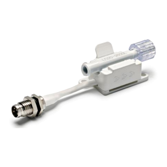
LD20 Base Station
Connector Block for Electrical Contact
Preface
The LD20 base station has been designed as an
easy-to-use tool for evaluating the LD20 liquid flow
sensor. The connector block performs two main
tasks: it mechanically fixates the sensor in place via
a clip-in mechanism and provides a simple electrical
interface between the contact pads of the sensor and
a PC or any other system for first bench-top tests.
Sensirion's base station is 3D-printed from Polyamid
and thus has to be handled with care.
The base station can be anchored to a test bench
using the integrated mounting holes.
1 Using the Sensirion LD20 Base Station
Please follow the steps below in using and handling the LD20 base station:
Connection:
Make sure all parts are clean and free of debris.
Check for the proper alignment of the LD20 sensor (1) : the orientation is correct if the contact pads of the flow
sensors are located on top of the spring pins and if the triangular recess of the LD20 sensor fits to the counterpart
on the base station. Press the LD20 flow sensor down into the base station (2).
All three versions of the LD20 series fit into the LD20 base station.
Connect the base station's male M8 with the SCC1-USB sensor cable for a plug-and-play connection with a PC.
You can connect any of Sensirion's SCC1 sensor cables as well, if you want to use analog voltage output signals
or RS485.
www.sensirion.com
D1
Figure 1: Proper alignment of the LD20 sensor to the Sensirion base station
The male M8 electrical connector is compatible with
Sensirion's SCC1 sensor cables.
Basic ESD protection is implemented as well.
The 3D-printed part is designed for testing purposes
only and will not be commercially available except as
part of the LD20 Evaluation Kit. Customers are
expected to refine the mechanical and electrical
interfaces to best suit their application needs within
their own base station design..
Version 1,
1/4
Advertisement

Related Manuals for SENSIRION LD20 Base Station


Summary of Contents for SENSIRION LD20 Base Station
- Page 1 Connect the base station’s male M8 with the SCC1-USB sensor cable for a plug-and-play connection with a PC. You can connect any of Sensirion’s SCC1 sensor cables as well, if you want to use analog voltage output signals or RS485.
- Page 2 The sensor will snap out. Handling and cleaning: The 3D-printed LD20 base station needs to be handled with proper care. Especially the clip is sensitive and could break off if too much force is applied, while disconnecting or connecting the sensor.
- Page 3 3 Engineering Guidelines for your LD20 Connector Block Sensirion’s LD20 base station is meant for testing purposes only, not for design-in. Thus, customers are expected to design their own LD20 connector block. The following engineering guidelines are provided for reference.
- Page 4 The following section describes the recommended way to electrically contact the LD20 sensor itself. Currently an electronic circuitry is built into Sensirion’s base station in order to stabilize the output signals, to have some ESD protection, and to provide a supply voltage buffer (see Figure 6). The resistors R3 and R4 drawn in grey are to be used as pull-up resistors for the I C interface.
Need help?
Do you have a question about the LD20 Base Station and is the answer not in the manual?
Questions and answers