Table of Contents
Troubleshooting

Related Manuals for Carlisle Ransburg IntelliFlow RM2

Summary of Contents for Carlisle Ransburg IntelliFlow RM2
- Page 1 USER MANUAL IntelliFlow ™ Low and Medium Pressure Scan the related QR code above for other languages of this RM2 low or medium pressure user manual and additional product information. 1/162 www.carlisleft.com 77-3153-R2 (03/2023)
-
Page 2: Table Of Contents
TABLE OF CONTENTS CONTENTS SAFETY Safety Precautions .............................. 4 Hazards/Safeguards ............................5-8 EU CONFORMITY 9-10 EU Declaration of Conformity ..........................9 Additional Safety Information ..........................10 INTRODUCTION 11-31 RM2 Low Pressure System Identifier ........................11 Features (Low Pressure) ............................ 12 System Components (Low Pressure) ........................13 System Configuration (Low Pressure) ......................... - Page 3 TABLE OF CONTENTS CONTENTS (cont.) OPERATION (cont.) Flow Meter ................................ 82 Multi-Color Status Light Functions ........................84 MAINTENANCE, TROUBLESHOOTING & SPARE PARTS 86-157 Alarm Troubleshooting (Low Pressure) ....................... 86 Dispense Pump Troubleshooting (Low Pressure) ....................89 Low Pressure Solenoid Connection Reference ...................... 90 Alarm Troubleshooting (Medium Pressure) ......................
-
Page 4: Safety
SAFETY PRECAUTIONS Before operating, maintaining or servicing any W A R N I N G Carlisle system, read and understand all of the The user MUST read and be familiar with the technical and safety literature for your Ransburg Safety Section in this manual and the Ransburg products. -
Page 5: Hazards/Safeguards
SAFETY AREA SAFEGUARDS HAZARD Tells where hazards Tells how to avoid the hazard. Tells what the hazard is. may occur. Fire Hazard Spray Area Fire extinguishing equipment must be present in the spray area and tested periodically. Improper or inadequate Spray areas must be kept clean to prevent the operation and accumulation of combustible residues. - Page 6 SAFETY AREA SAFEGUARDS HAZARD Tells where hazards Tells how to avoid the hazard. Tells what the hazard is. may occur. Unless specifically approved for use in hazardous Electrical Electrical Discharge locations, the power supply, control cabinet, and Equipment all other electrical equipment must be located High voltage equipment is utilized in the process.
-
Page 7: Eu Declaration Of Conformity
EU DECLARATION OF CONFORMITY 7/162 www.carlisleft.com 77-3153-R2 (03/2023) - Page 8 SAFETY AREA SAFEGUARDS HAZARD Tells where hazards Tells how to avoid the hazard. Tells what the hazard is. may occur. Electrostatic arcing must be prevented. Safe Spray Area Explosion Hazard sparking distance must be maintained between the parts being coated and the applicator. A Improper or inadequate distance of 1 inch for every 10KV of output operation and...
-
Page 9: Eu Conformity
SAFETY AREA SAFEGUARDS HAZARD Tells where hazards Tells how to avoid the hazard. Tells what the hazard is. may occur. Spray Area Electrical Discharge Parts being sprayed and operators in the spray area must be properly grounded. High Voltage There is a high voltage Parts being sprayed must be supported on device that can induce an Equipment... -
Page 10: Additional Safety Information
SAFETY CAUTION Do not operate the RM2 before reading this section. ADDITIONAL SAFETY INFORMATION The RM2 has a main operator panel emergency stop (E-Stop) pushbutton included with the unit. In the event of a safety fault, all operations for the RM2 will halt, all solenoid outputs will be turned off, and all pressure pilot signals will go to zero psi/BAR. -
Page 11: Rm2 Low Pressure System Identifier
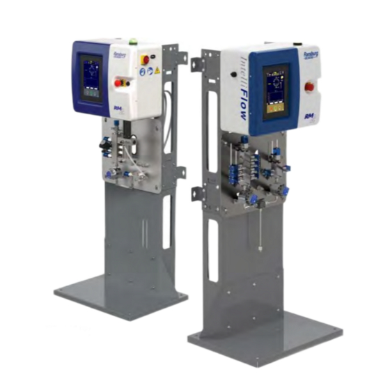
INTRODUCTION — RM2 LOW PRESSURE RM2 LOW PRESSURE The low pressure RM2 model can be easily determined by looking at the fluid panel. The low pressure RM2 has a dispense pump (1) on the right hand side of the fluid panel. Use this book section if your RM2 has this pump type. -
Page 12: Introduction
INTRODUCTION — RM2 LOW PRESSURE INTRODUCTION The RM2 system is designed to accurately mix most two component (2K) and one component (1K) paints. It will supply any low-pressure manual or automatic spray gun and can easily handle very low flow rates or high ratio materials (greater than 20:1). -
Page 13: System Components (Low Pressure)
INTRODUCTION — RM2 LOW PRESSURE SYSTEM COMPONENTS 1. Control Panel 2. Fluid Control Module 3. Mix Manifold 4. Pedestal (Optional) CONTROL PANEL External Components 1. Status light 2. Main power entry 3. Main power disconnect switch 4. Panel opening latch 5. - Page 14 INTRODUCTION — RM2 LOW PRESSURE Internal Components 1. Solenoid stack 2. USB flash drive 3. Linear actuator 4. Air flow switches 5. Main power disconnect switch connector 6. Connection to status light 7. Connection to HMI and emergency stop button 8.
-
Page 15: System Configuration (Low Pressure)
INTRODUCTION — RM2 LOW PRESSURE SYSTEM CONFIGURATION Air Supply 1. Valve stack solenoid manifold Solent Supply 2. Material A valve stack Material A lines 3. Material dispense pump Material B lines 4. Mix Manifold Mixed material lines 15/162 www.carlisleft.com 77-3153-R2 (03/2023) -
Page 16: Theory Of Operation (Low Pressure)
INTRODUCTION — RM2 LOW PRESSURE THEORY OF OPERATION The RM2’s operating principle is as follows: 1. The material is fed through the hoses towards the material valves in the color stack, and the hardener dispense pump. 2. The color stack and resin enable valve control material flow on the resin side. The dispense pump controls hardener material flow. - Page 17 INTRODUCTION — RM2 LOW PRESSURE 7. The material proceeds to the mix block where the individual components are introduced before the static mixer. The resin enters the mix block through a resin enable valve and the hardener enters through an injector valve.
- Page 18 Page is intentionally left blank. 18/162 77-3153-R2 (03/2023) www.carlisleft.com...
-
Page 19: Rm2 Medium Pressure System Identifier
INTRODUCTION — RM2 MEDIUM PRESSURE RM2 MEDIUM PRESSURE The medium pressure RM2 model can be easily determined by looking at the fluid panel. The medium pressure RM2 has a pulse valve assembly (1) on the right hand side of the fluid panel. Use this book section if your RM2 has this valve. -
Page 20: Features (Medium Pressure)
INTRODUCTION — RM2 MEDIUM PRESSURE INTRODUCTION The RM2 system is designed to accurately mix most two component (2K) and one component (1K) paints. It will supply any medium-pressure manual or automatic spray gun and can easily handle very high flow rates or high ratio materials (greater than 20:1). -
Page 21: System Components (Medium Pressure)
INTRODUCTION — RM2 MEDIUM PRESSURE SYSTEM COMPONENTS 1. Control Panel 2. Fluid Control Module 3. Pulse Valve Assembly 4. Pedestal (Optional) CONTROL PANEL External Components 1. Status light 2. Main power entry 3. Main power disconnect switch 4. Panel opening latch 5. - Page 22 INTRODUCTION — RM2 MEDIUM PRESSURE INTERNALCOMPONENTS 1. Solenoid stack 2. USB flash drive 3. Air flow switches 4. Main power disconnect switch connector 5. Connection to status light 6. Connection to HMI and emergency stop button 7. HMI (Internal) 8. IO block 9.
-
Page 23: System Configuration (Medium Pressure)
INTRODUCTION — RM2 MEDIUM PRESSURE SYSTEM CONFIGURATION Air Supply 1. Valve stack solenoid manifold Solvent Supply 2. Material A valve stack Material A lines 3. Pulse valve stack Material B lines 4. Mix Manifold Mixed material lines 23/162 www.carlisleft.com 77-3153-R2 (03/2023) -
Page 24: Theory Of Operation (Medium Pressure)
INTRODUCTION — RM2 MEDIUM PRESSURE THEORY OF OPERATION The RM2’s operating principle is as follows: 1. The material is fed through the hoses towards the material valves in the color stack, and the pulse valve. 2. The color stack and resin enable valve control material flow on the resin side. The pulse valve controls hardener material flow. - Page 25 INTRODUCTION — RM2 MEDIUM PRESSURE 7. The material proceeds to the mix block where the individual components are introduced before the static mixer. The resin enters the mix block through a resin enable valve and the hardener enters through an injector valve.
-
Page 26: Rm2 Main Air, Gun Flush, And Atomizing Air Connections
INTRODUCTION RM2 MAIN AIR, GUN FLUSH, AND ATOM AIR CONNECTIONS 4mm OD tube (to gun flush box) 4mm OD tube (to gun trigger solenoid) 6mm OD tube (to solenoids) 4mm OD tube (to GIB pressure switch) Atomization air line (to 4mm OD tube (to ACO air flow switches) switch) -
Page 27: Complete System Part Numbering
INTRODUCTION COMPLETE SYSTEM PART NUMBERING # # # # # of Colors Pressure Compatibility Flowmeter Dispensing 0= No color stack 1= 250 PSI 1= Standard 0= None 1= 600 CC 1= 1 Color 2= 3,000 PSI 2= Acid 1= Gear 2= 300 CC 3= 3 Colors 2= Coriolis... -
Page 28: Technical Specifications-Low Pressure
INTRODUCTION TECHNICAL SPECIFICATIONS-LOW PRESSURE Item Details Max working air pressure 105 psi (7.2 bar) Optimal working air pressure 75-105 psi (5.2-7.2 bar) Pressure rating 250 psi (17.2 bar) Max dispense pump flow rate 10.1 or 20.3 oz/min (300 or 600 cc/m) RM2 low pressure Min dispense pump flow rate 0.07 or 0.7 oz/min (2 or 20 cc/min) -
Page 29: Technical Specifications-Medium Pressure
INTRODUCTION TECHNICAL SPECIFICATIONS-MEDIUM PRESSURE Item Details Max working air pressure 105 psi (7.2 bar) Optimal working air pressure 75-105 psi (5.2-7.2 bar) Pressure rating 3000 psi (206.85 bar) Max pulse valve flow rate 64 oz/min (1900 cc/m) RM2 medium pressure Min pulse valve flow rate 0.34 oz/min (10 cc/min) RM2 medium pressure... -
Page 30: Wall Mount Dimensions
INTRODUCTION TECHNICAL SPECIFICATIONS-LOW PRESSURE WALL MOUNT DIMENSIONS Requirements: Make sure wall is able to support weight of complete system, including air and fluid hoses and other • connected devices. Minimum 91 kg (200 lbs.). Make sure clearance for electrical and fluid connections to system, and door swing radius. •... -
Page 31: Floor Stand Dimensions (Optional)
INTRODUCTION FLOOR STAND DIMENSIONS (OPTIONAL) Requirements: Stand should be bolted to the floor. • Floor stand kit 240-5199 • 31/162 www.carlisleft.com 77-3153-R2 (03/2023) - Page 32 Page is intentionally left blank. 32/162 77-3153-R2 (03/2023) www.carlisleft.com...
-
Page 33: Installation
INSTALLATION INSTALLATION Before operating the RM2, Make sure all the below installation steps are complete. Schematics and further information are provided separately from this manual. ELECTRICAL The RM2 can accept either 120VAC or 240VAC as a power source. The internal 24VDC power supply automatically detects the input voltage and produces control power accordingly. -
Page 34: Pneumatics (Low Pressure)
INSTALLATION — RM2 LOW PRESSURE Electrical Connection 1. Locate the main power entry plug (a) in the upper right section of the cabinet 2. Locate the disconnect switch connector (b) inside of the control panel 3. Make sure the main power entry plug is connected at the top (c), opposite their secondary connections (d) below. - Page 35 INSTALLATION — RM2 LOW PRESSURE 5. Attach a final 3/8" main air line in the front panel connector (c) that will lead to the gun’s air input. Solenoid Air Input 1. Locate the air inlet connection on the back of the system chassis (a). 2.
- Page 36 INSTALLATION — RM2 LOW PRESSURE 1. Locate the Material A valve stack (a). 2. Locate the top left valve (b). 3. Using a 3/8" air line, connect your air source to the valve (c). Internal Air Connections NOTE It is recommended to install an air pressure regulator between your air source and the air valve to monitor maximum air pressure.
-
Page 37: Paint Materials (Low Pressure)
INSTALLATION — RM2 LOW PRESSURE PAINT MATERIALS Your system may include up to 7 material valves. The process to connect each is the same; repeat the steps below as needed. The number of valves on the stack will depend on your application and needs. Paint resins and hardeners may be supplied to the RM2 system via pressure tanks or pumps. -
Page 38: Disposal Information (Low Pressure)
INSTALLATION — RM2 LOW PRESSURE 7. Connect your material B hose into the pump inlet. 8. Connect a material hose between the pump outlet (g) and the second mix block connector (h). 9. Connect the mix block to the mixing tube (i) using the bottom connector (j). -
Page 39: Electrical (Medium Pressure)
INSTALLATION — RM2 MEDIUM PRESSURE INSTALLATION Before operating the RM2, Make sure all the below installation steps are complete. Schematics and further information are provided separately from this manual. ELECTRICAL The RM2 can accept either 120VAC or 240VAC as a power source. Its internal 24VDC power supply automatically detects the input voltage and produces control power accordingly. -
Page 40: Pneumatics (Medium Pressure)
INSTALLATION — RM2 MEDIUM PRESSURE Electrical Connection 1. Locate the main power entry plug (a) in the upper right section of the cabinet 2. Locate the disconnect switch connector (b) inside of the control panel 3. Make sure the main power entry plug is connected at the top (c), opposite their secondary connections (d) below. - Page 41 INSTALLATION — RM2 MEDIUM PRESSURE 5. Attach a final 3/8" main air line in the front panel connector (c) that will lead to the gun’s air input. Solenoid Air Input 1. Locate the air inlet connection on the back of the system chassis (a). 2.
- Page 42 INSTALLATION — RM2 MEDIUM PRESSURE Material A Air Input 1. Locate the Material A valve stack (a). 2. Locate the top left valve (b). 3. Using a 3/8" air line, connect your air source to the valve (c). NOTE It is recommended to install an air pressure regulator between your air source and the air valve to monitor maximum air pressure.
-
Page 43: Paint Materials (Medium Pressure)
INSTALLATION — RM2 MEDIUM PRESSURE PAINT MATERIALS Your system may include up to 7 material valves. The process to connect each is the same; repeat the steps below as needed. The number of valves on each stack will depend on your application and needs. Paint resins and hardeners may be supplied to the RM2 system via pressure tanks or pumps. -
Page 44: Disposal Information (Medium Pressure)
INSTALLATION — RM2 MEDIUM PRESSURE 1. Locate the material B pulse valve input connectors (f). 2. Connect your material B hoses into the pulse valve inlets. 3. Locate the material B solvent pulse valve input connector (g). Connect your material B solvent hose into the solvent pulse valve inlet. -
Page 45: Rm2 Cloud Setup
INSTALLATION RM2 CLOUD SETUP 1. Login to ‘admin’ user. 2. Select Menu > Setup > Exor Internal Menu. 3. Select > Show system settings. 45/162 www.carlisleft.com 77-3153-R2 (03/2023) - Page 46 INSTALLATION 4. Select “Network.” 5. Select “Edit.” 46/162 77-3153-R2 (03/2023) www.carlisleft.com...
- Page 47 INSTALLATION 6. Enter Network and network password. Click “Save.” 7. Click “Menu” at the top left. Select “Services.” 47/162 www.carlisleft.com 77-3153-R2 (03/2023)
- Page 48 8. Enable these three (3) services: a) VNC Service, b) Router/NAT/Port Forwarding c) Cloud/VPN Service 9. In “Cloud/VPN” verify the following settings: Server: us.corvinacloud.com Username: RM2-machineserialnumber/organization For example: RM2-1234/CFTLiquid Password: paint123$ NOTE Login credentials will be different for each machine based upon the following: your machine serial number, and your organization’s server or cloud login credentials.
-
Page 49: Operation Powering Up The System
OPERATION OPERATION POWERING UP THE SYSTEM Before powering-up the system, Make sure that main power has been installed correctly. See section on electric installation for more details. To power-up: 1. On the righthand side of the control module enclosure, turn the rotary disconnect switch clockwise. The system will go through a boot-up sequence. - Page 50 OPERATION NAVIGATION BAR Except on certain menus that have special purposes, the navigation bar shown below will be visible in the upper section of the screen. Each section will be discussed separately in this manual. Access Access Drop-down Login/User Alarm Menu actions menu...
- Page 51 OPERATION — RM2 LOW PRESSURE Color Change Screen The color change screen is used for changing colors and flushing the system with the flush/load sequence programmed in the settings screen. Displays the Color current color selection for loaded in color the system switching Time frames...
- Page 52 OPERATION — RM2 MEDIUM PRESSURE Color Change Screen The color change screen is used for changing colors and flushing the system with the flush/load sequence programmed in the settings screen. Displays the current fluid flow rate Displays the current color loaded in the system Gun 1/2...
- Page 53 OPERATION Alarms Screen This screen displays all of the available system alarms (a). If an alarm sounds it will be highlighted, and the Reset button in the main spray screen must be pushed before the system can spray again. Alarm history (b) is also saved in this screen.
- Page 54 OPERATION — RM2 LOW PRESSURE Prime Screen-Low Pressure Use this screen to prime the RM2 unit with Resin (A) and Hardener (B). Buttons will independently operate the Resin color valves (A0-A9), or the dispense pump for material loading. Gun atomizing air must be off while priming.
- Page 55 OPERATION — RM2 MEDIUM PRESSURE Prime Screen-Medium Pressure Use this screen to prime the RM2 unit with Resin (A) and Hardener (B). Buttons will independently operate the Resin color valves (A0-A9), or the pulse valves for material loading. Gun atomizing air must be off while priming.
- Page 56 OPERATION — RM2 MEDIUM PRESSURE Prime Screen-Medium Pressure Use this screen to prime the RM2 unit with Hardener (B). Buttons will independently operate the hardener pulse valves for material loading. Gun atomizing air must be off while priming. Press button to open material B pulse valves.
- Page 57 OPERATION Settings Screen Select the settings button from the dropdown menu to access system settings. Before opening this screen a password prompt for access will take over the screen. Viewing or changing settings requires user permissions (varied between normal users and administrators). Each screen will be reviewed separately in the next pages of this manual.
- Page 58 OPERATION User Options 1. To access the user options page, log in as an administrator and then press the ‘user’ (a) menu key in the navigation bar to open the user actions dialog. 2. A dialog box will open and the administrator will see an option called ‘User Options’ (b). 3.
- Page 59 OPERATION Add User The operator interface supports up to fifty individual users. To add a user, enter the Add User menu. Fill in the parameters (i) including user name, group assignment and initial password. Delete User To delete a user, enter the Delete User menu.
- Page 60 OPERATION Exor Internal Menu The Exor (1) dropdown dialog (2) allows access to the root settings for the Exor operator interface’s internal settings. Setting IP addresses for the three networks provided with the interface (described in the Installation section above), and setting the date and time displayed on the panel are the only operations that are necessary to operate the RM2.
- Page 61 OPERATION — RM2 LOW PRESSURE The parameters are: a. System Max Pressure: Select the maximum fluid pressure that is allowed according to the hardware installed. b. Cylinder Volume: 300cc or 600cc pumps are available. c. A (resin) Flow Meter: Select the flowmeter type that has been installed.
- Page 62 OPERATION — RM2 LOW PRESSURE System Settings Pressing the System Settings button (5) in the fluid system group, will open up the settings screen to the right. Some of these set values will trigger alarms on the system when upper or lower limits are exceeded during operations.
- Page 63 OPERATION — RM2 MEDIUM PRESSURE The parameters are: a. System Type: Select the type of pump action. b. Pulse Valves: 1 or 2 pulse valves are available. c. A (resin) Flow Meter: Select the flowmeter type that has been installed. Standard installations will use Gear A/B (quadrature) flowmeters, but Coriolis meters are also an option.
- Page 64 OPERATION — RM2 MEDIUM PRESSURE System Settings Pressing the System Settings button (5) in the fluid system group, will open up the settings screen to the right. Some of these set values will trigger alarms on the system when upper or lower limits are exceeded during operations.
- Page 65 OPERATION — RM2 MEDIUM PRESSURE CCV Pulse Flow Adjustment-Below Range The correct pulse flow range is in the green zone as shown between the green arrows. In the image shown at the right, the blue diamond shape is left of the green zone and below range. The flow must be increased to a specified 50%.
- Page 66 OPERATION — RM2 MEDIUM PRESSURE CCV Pulse Flow Adjustment-Above Range The correct pulse flow range is in the green zone as shown between the green arrows. In the image shown at the right, the blue diamond shape is right of the green zone and above range. The flow must be decreased to a specified 50%.
- Page 67 OPERATION — RM2 MEDIUM PRESSURE CCV Pulse Flow Adjustment-In Range The correct pulse flow range is in the green zone as shown between the green arrows. In the image shown at the right, the blue diamond shape is in the center of the green zone and is in range.
- Page 68 OPERATION Cycle Counter This menu (8) displays the amount of times each solenoid in the system has been activated. If desired (due to replacement of a solenoid for example) to reset these values, select each field to be reset by pressing and highlighting the icon to the left of the value and press and hold the ‘Reset’...
- Page 69 If it is suspected that someone has unauthorized access to your RM2. Contact your Corvina Cloud organization’s administrator (This could be the distributor of your equipment). If this information is not known, contact Carlisle Fluid Technologies. Alarm Masking This menu (4) allows individual system alarms to be treated as a ‘fault’ (a) which will shut down system operation, or ‘warning’...
- Page 70 OPERATION Language Pressing the Language button (10) in the Global Configuration group, will open up the Language change dialog. You can also access these options from the Dropdown menu of the navigation bar in the bottom button. Choose the preferred language by clicking in the corresponding flag.
- Page 71 OPERATION The Remote Color Change Box is an optional purchase compatible with this system. The color-change controller is connected through an Intrinsic Barrier (Zener Barrier) located outside the hazardous area to the RM2 device. Instructions for installation of the remote color change box are included with it.
- Page 72 OPERATION used, total available memory in MB, the operating system version and Runtime version. This screen is automatically updated with the latest information when being updated. Recipe Screen The Recipe Menu allows set up of parameters that are specific to resins that are loaded. In the top part of the menu are material parameters—these are: Type (1K or 2K): If 1K, the catalyst pump will not be activated (no mixing will be required) but flow rates will be measured and recorded and resin-max flow alarm will still be active.
- Page 73 OPERATION Flushing Recommendations Suggested Initial Name Description Setting First Flush Air or Solvent to initially flush fluid lines. Duration of first flush. This flush is used to move paint First Flush Time 15 seconds out of the system before attempting to “clean” with the Air Chop Time 1 second Duration of each air burst in the chop process...
- Page 74 OPERATION Reports Screen This menu allows process data to be tracked by ‘jobs’ that can be stored to a USB stick if installed in the HMI USB Slot. Job files in CSV format can be removed from the USB stick and stored and viewed through a CSV viewing software such as MS Excel.
-
Page 75: Startup Guide
OPERATION STARTUP GUIDE Use the following pages as a quick reference to make electrical, air, and fluid connections to the RM2 and begin operation. Familiarize with the configuration of the machine and any options or accessories attached. Return to the User Interface Guide section of this manual for information on configuration and settings. Startup Checklist Verify the frame is secured to the ground or wall and that all components are mounted securely to the enclosure, fluid panel or mast. - Page 76 OPERATION Startup Procedure When air and material connections have been tested 13. When spraying is complete, shut off atomizing air for leaks the machine should be ready to power on. and perform a color change or flush as required. Startup for systems with gun flush boxes Startup for systems without gun flush boxes 1.
-
Page 77: Daily Operations
OPERATION DAILY OPERATIONS Daily use of the RM2 system involves several procedures. Understanding how the system works and knowing the properties of the paint materials in use is the best way to Make sure continuous use with few alarms and repairs. - Page 78 OPERATION Loading a Color 1. Follow steps 1 through 8 of the Daily Start Up Procedure section before proceeding. 2. Go to the Home screen and Make sure atomizing air is turned off. For systems with gun flush boxes, place the gun in the box and close the lid.
- Page 79 OPERATION End of Day Flushing Procedure To shut down the machine for longer periods or overnight follow the steps below. 1. Flush the Mixed Material using one of the methods below. a. Color 0 Load: Perform a color 0 load to clear the fluid lines of material and load with solvent. For information on loading, see Loading a Color.
- Page 80 OPERATION System Depressurization Process 1. Flush the system if it will not be used for extended periods. Make sure all guns are in gun flush boxes, and that lids are securely closed. If not using flush boxes or ACO, shut off atomizing air for the next steps and use a grounded metal waste container.
-
Page 81: Dispense Pump Operation
OPERATION — RM2 LOW PRESSURE DISPENSE PUMP OPERATION Material is delivered to be mixed by a piston and cylinder dispense pump. An inlet and an outlet valve on each end of the pump controls the material flow. When the piston is moving down, the bottom inlet valve is closed, and the bottom outlet valve is open. -
Page 82: Operation (Cont.)
OPERATION FLOW METER The flow meter is a gear-type positive displacement meter specially designed for paint and will measure flow up to 1900cc per minute. A sensor detects the movement of the inner gears and sends an electronic signal in the form of a pulse to the controller. - Page 83 OPERATION Flow Meter Calibration For the best accuracy in ratio performance of the RM2, it is necessary to calibrate the flowmeter per the material that is being used. The calibration menu can be reached through the recipe menu and allows a quick check of the material volume dispensed versus what is calculated.
-
Page 84: Multi-Color Status Light Functions
OPERATION MULTI-COLOR STATUS LIGHT FUNCTIONS The status light is found on the top of the exterior of the RM2 control panel. The light will change color and/ or flash depending on the status of the RM2. Each light function is defined below. Light Function Green—Solid... - Page 85 Page is intentionally left blank. 85/162 www.carlisleft.com 77-3153-R2 (03/2023)
-
Page 86: Maintenance, Troubleshooting & Spare Parts
MAINTENANCE — RM2 LOW PRESSURE MAINTENANCE, TROUBLESHOOTING & SPARE PARTS Although the RM2 is a complex machine, troubleshooting the unit is straightforward, with a few basic steps. ALARM TROUBLESHOOTING The alarm dialog is the first indication that something may be wrong with the RM2 control processes. Below is a list of alarms and troubleshooting steps. - Page 87 MAINTENANCE — RM2 LOW PRESSURE Alarm Message Alarm Condition(s) Action(s) Check electrical connection and wiring Improper electrical signal from upper Upper Transducer Fault Confirm upper pressure transducer on dispense pump pressure transducer on correctly functions dispense pump Check electrical connection and wiring Improper electrical signal from lower Lower Transducer Fault...
- Page 88 MAINTENANCE — RM2 LOW PRESSURE Alarm Message Alarm Condition(s) Action(s) Confirm stop button was not pressed Confirm atomization air is not detected during color change Color change sequence Color Change Fault If equipped-Confirm applicator(s) are in gun flush box(s) has been interrupted and lid(s) are closed If equipped-Confirm proper operation of gun flush box(s) Check for air in fluid lines to color stack valves...
-
Page 89: Dispense Pump Troubleshooting (Low Pressure)
MAINTENANCE — RM2 LOW PRESSURE DISPENSE PUMP TROUBLESHOOTING Use this checklist to help identify potential problems with the dispense pump-avoid unnecessary disassembly. If the problem is still not corrected, it may be necessary to remove the dispense pump and clean it thoroughly after flushing it with a solvent. -
Page 90: Low Pressure Solenoid Connection Reference
MAINTENANCE — RM2 LOW PRESSURE LOW PRESSURE SOLENOID CONNECTION REFERENCE Use the reference below to reconnect the solenoid air lines to their bulkheads and CCVs. Units that are not fully optioned may not have all 15 solenoids. Solenoid #/CCV Location Description Basic Optioned Dispense Pump... - Page 91 Page is intentionally left blank. 91/162 www.carlisleft.com 77-3153-R2 (03/2023)
-
Page 92: Alarm Troubleshooting (Medium Pressure)
MAINTENANCE — RM2 MEDIUM PRESSURE MAINTENANCE, TROUBLESHOOTING & SPARE PARTS ALARM TROUBLESHOOTING System alarms are used to alert the user to conditions which may result in off-ratio spraying or fluid pressure out of range. Refer to the table below to troubleshoot RM2 alarms. Troubleshooting suggestions are listed in order of difficulty with the easier solutions presented first. - Page 93 MAINTENANCE — RM2 MEDIUM PRESSURE Alarm Message Alarm Condition(s) Action(s) Confirm upper pressure transducer on the CCV pulse valve Improper electrical signal assembly correctly functions from upper pressure Upper Transducer Fault transducer on the CCV Confirm upper pressure transducer on the CCV pulse valve pulse valves assembly correctly functions Improper electrical signal...
-
Page 94: Power Outage Cleaning Procedure
MAINTENANCE — RM2 MEDIUM PRESSURE Alarm Message Alarm Condition(s) Action(s) Check component B supply for fluid leaks Confirm component B supply valve is open and the supply is adequate Confirm component B pressure is correct Component B flow Adjust flow sensor so display returns to red signal after spray detected without CCV Component B Flow Fault applicator stops triggering... -
Page 95: Medium Pressure Solenoid Connection Reference
MAINTENANCE — RM2 MEDIUM PRESSURE MEDIUM PRESSURE SOLENOID CONNECTION REFERENCE Use the reference below to reconnect the solenoid air lines to their bulkheads and CCVs. Units that are not fully optioned may not have all 18 solenoids. Solenoid #/CCV Location Description Basic Optioned PULSE 1... -
Page 96: Flow Meter Troubleshooting
MAINTENANCE FLOW METER TROUBLESHOOTING Flowmeter problems can be caused by improperly filtered fluid. Particulates in the fluid can cause gear binding, resulting in improper signals for the actual flow rate. Maintain the fluid filters according to the instructions from the filter manufacturer. If repeated disassembly and cleaning for removal of solids and particulates occurs, inspect the entire fluid supply system and evaluate the system cleaning cycle. -
Page 97: Maintenance Procedures
MAINTENANCE MAINTENANCE PROCEDURES There are no enclosure components which should require cleaning if the enclosure door is kept shut. If material seepage occurs, be sure to correct the problem and maintain a clean work area. To avoid hardening of the paint inside the fluid lines, the system must be cleaned by a complete flushing procedure at the end of operations. -
Page 98: Preventive Maintenance
MAINTENANCE PREVENTIVE MAINTENANCE The RM2 system requires periodic inspection and regular maintenance. Follow the corresponding table as a guide to perform routine maintenance at suggested intervals. These intervals are recommendations and largely depend on the material being sprayed. Daily/Each Shift: Make sure mixed material is properly flushed at the end of the shift. -
Page 99: Regular Inspections
MAINTENANCE REGULAR INSPECTION Continuous use or lack of use of the system may both lead to system malfunctioning. Refer to the frequency table below and do regular inspections to the system. Frequency Description Inspection Method Daily System flushed with solvent Visual Daily Examine for leaks... -
Page 100: Component View And Spare Parts
MAINTENANCE — RM2 LOW PRESSURE COMPONENT VIEWS & SPARE PARTS Item No. Part No. Description Qty. 240-3122-300 Static Mix Assembly, 300cc 240-3122-600 Static Mix Assembly, 600cc 240-5136-300 300cc Dispense Pump as desired 240-5136-600 600cc Dispense Pump 240-5141 300cc Pump Rebuild Kit 240-5142 600cc Pump Rebuild Kit 240-5156... - Page 101 MAINTENANCE — RM2 LOW PRESSURE Item No. Part No. Description Qty. 240-3047 Injector Valve Assembly 240-5154 Solenoid Valve Slice A10756-00 Tool, MCV removal 240-5290 JP - Cord w/ Connector 240-5291 NA - Cord w/ Connector 240-5292 UK - Cord w/ Connector 240-5293 CN - Cord w/ Connector 240-5294...
- Page 102 MAINTENANCE — RM2 LOW PRESSURE DISPENSE PUMP Item No. Part No. Description Qty. Notes 240-3020 Pump Rod Adapter 20-6953 Hex Nut 237-729 Retaining Ring 237-727 Flat Washer 240-3084 Seal Holder Assembly 240-3211 Rod Seal 79001-09 O-Ring, 2-015, FFKM 240-3116 Elbow, 10-32 x 1/4” ODT FEP-0402 FEP Tubing, 1/4”...
- Page 103 MAINTENANCE — RM2 LOW PRESSURE * 4” total, 2” per side, buy length and cut to length ** Item is not used on 240-3015-300 103/162 www.carlisleft.com 77-3153-R2 (03/2023)
- Page 104 MAINTENANCE — RM2 LOW PRESSURE MIX MANIFOLD ASSEMBLY-LOW PRESSURE Item No. Part No. Description Qty. Notes 41-FTP-1006 FTG BRA 5/32 OTD x 1/8 NPT (M) EL 14.9-17.6 N • ‡ CCV-503-SS Valve Assembly (see next page) (132-156 in-lbs) Check Valve SSV-809 Adapter, MM 1/8 NPT x 3/8 NPS 2T-6 (F)
- Page 105 MAINTENANCE — RM2 LOW PRESSURE 105/162 www.carlisleft.com 77-3153-R2 (03/2023)
- Page 106 MAINTENANCE — RM2 LOW PRESSURE CCV VALVE ASSEMBLY-LOW PRESSURE Item No. Part No. Description Qty. Notes 8.5-14.0 N • CCV-43-1 End Cap, Aluminum, Anodized Blue (75-125 in-lbs) 0.2-0.5 N • CCV-45 Nut, Clamping, Brass (2-4 in-lbs) VA-246 Cup, Sealing, Teflon 1.4-2.0 N •...
- Page 107 MAINTENANCE — RM2 LOW PRESSURE 107/162 www.carlisleft.com 77-3153-R2 (03/2023)
- Page 108 MAINTENANCE — RM2 MEDIUM PRESSURE COMPONENT VIEWS & SPARE PARTS Item No. Part No. Description Qty. 240-3231 Static Mixer, Medium Pressure Assembly 72-727 Adapter, 1/8" NPT (F) x 1/4" NPS (M) 204-3234 Adapter, 6JIC (M) X 1/8 NPT (F) 240-5156 15 PSI Pressure Switch 240-5180 Circuit Breaker Kit 1077 1P, Plug 2A...
- Page 109 MAINTENANCE — RM2 MEDIUM PRESSURE Item No. Part No. Description Qty. — 0114-016099 Throat Seal Lube, Solvent-Based — 0114-016100 Throat Seal Lube, Water-Based 10 11 10 11 18 19 20 18 20 11 12 14 15 16 10 11 12 14 15 16 21 22 24 25...
- Page 110 MAINTENANCE — RM2 MEDIUM PRESSURE CVV PULSE VALVES Item No. Part No. Description Qty. Notes 240-2059 Pump Rod Adapter 1◊ 240-2058 Hex Nut 1◊ 240-2026 Socket Head Cap Screw, SS, M4 x .7 x 45 240-2017 End Cap 240-2036 Circlip 1◊...
- Page 111 MAINTENANCE — RM2 MEDIUM PRESSURE 111/162 www.carlisleft.com 77-3153-R2 (03/2023)
- Page 112 MAINTENANCE — RM2 MEDIUM PRESSURE MIX MANIFOLD ASSEMBLY-MEDIUM PRESSURE Item No. Part No. Description Qty. Notes Mix Manifold Housing 240-5359 PDHC-04-KK- 1/4 NOMID X 12 in OAL W-4SS FNPS Body Check Valve, Medium Pressure, 3/8” 22-863-3 Retainer, Spring 240-3044 Spring 240-3045 O Ring, 2-008, Perfluoroelastomer 79001-04...
- Page 113 MAINTENANCE — RM2 MEDIUM PRESSURE 113/162 www.carlisleft.com 77-3153-R2 (03/2023)
-
Page 114: Electrical Diagrams-Low Pressure
MAINTENANCE — RM2 LOW PRESSURE ELECTRICAL DIAGRAMS-LOW PRESSURE FLOW METER Drawing # Description General Specifications Schematic Descriptions EMI Filter Power Distribution Power Distribution 24VDC 5-18 Machine Control 19, 20 Communication/Networking WIRE GAUGE (UNLESS NOTED) USE MIN 75 DEGREE C COPPER WIRE American Wire Gauge Diameter Cross Sectional Area... - Page 115 MAINTENANCE — RM2 LOW PRESSURE WIRE REFERENCE COLOR Black White Blue Green Orange Brown Yellow WIRE REFERENCE COLOR RED_GRY RED w/GREY STRIPE GRY_RED GREY w/WHITE STRIPE WHT_BRN WHITE w/BROWN STRIPE BRN_WHT BROWN w/WHITE STRIPE WHT_GRY WHITE w/GREY STRIPE GRY_WHT GREY w/WHITE STRIPE RED_BLU RED w/BLUE STRIPE BLU/RED...
- Page 116 MAINTENANCE — RM2 LOW PRESSURE CABLE NUMBER CABLE TYPE PART NUMBER CBL4004 CAT6 CBL4208 FACTORY CABLE CBL4211 FACTORY CABLE CBL4214 CBL4302 FACTORY CABLE CBL4408 FACTORY CABLE 240-5222 CBL4420 FACTORY CABLE CBL4511 BULK CABLE CBL4517 FACTORY CABLE 240-5187 CBL4520 FACTORY CABLE 240-5187 CBL4602 FACTORY CABLE...
- Page 117 MAINTENANCE — RM2 LOW PRESSURE DRAWING 1 117/162 www.carlisleft.com 77-3153-R2 (03/2023)
- Page 118 MAINTENANCE — RM2 LOW PRESSURE DRAWING 2 118/162 77-3153-R2 (03/2023) www.carlisleft.com...
- Page 119 Page is intentionally left blank. 119/162 www.carlisleft.com 77-3153-R2 (03/2023)
- Page 120 MAINTENANCE — RM2 LOW PRESSURE DRAWING 3 120/162 77-3153-R2 (03/2023) www.carlisleft.com...
- Page 121 MAINTENANCE — RM2 LOW PRESSURE DRAWING 4 121/162 www.carlisleft.com 77-3153-R2 (03/2023)
- Page 122 MAINTENANCE — RM2 LOW PRESSURE DRAWING 5 122/162 77-3153-R2 (03/2023) www.carlisleft.com...
- Page 123 MAINTENANCE — RM2 LOW PRESSURE DRAWING 6 123/162 www.carlisleft.com 77-3153-R2 (03/2023)
- Page 124 MAINTENANCE — RM2 LOW PRESSURE DRAWING 7 124/162 77-3153-R2 (03/2023) www.carlisleft.com...
- Page 125 MAINTENANCE — RM2 LOW PRESSURE DRAWING 8 125/162 www.carlisleft.com 77-3153-R2 (03/2023)
- Page 126 MAINTENANCE — RM2 LOW PRESSURE DRAWING 9 126/162 77-3153-R2 (03/2023) www.carlisleft.com...
- Page 127 MAINTENANCE — RM2 LOW PRESSURE DRAWING 10 127/162 www.carlisleft.com 77-3153-R2 (03/2023)
- Page 128 MAINTENANCE — RM2 LOW PRESSURE DRAWING 11 128/162 77-3153-R2 (03/2023) www.carlisleft.com...
- Page 129 MAINTENANCE — RM2 LOW PRESSURE DRAWING 12 129/162 www.carlisleft.com 77-3153-R2 (03/2023)
- Page 130 MAINTENANCE — RM2 LOW PRESSURE DRAWING 13 130/162 77-3153-R2 (03/2023) www.carlisleft.com...
- Page 131 MAINTENANCE — RM2 LOW PRESSURE DRAWING 14 131/162 www.carlisleft.com 77-3153-R2 (03/2023)
- Page 132 MAINTENANCE — RM2 LOW PRESSURE DRAWING 15 132/162 77-3153-R2 (03/2023) www.carlisleft.com...
- Page 133 MAINTENANCE — RM2 LOW PRESSURE DRAWING 16 133/162 www.carlisleft.com 77-3153-R2 (03/2023)
- Page 134 MAINTENANCE — RM2 LOW PRESSURE DRAWING 17 134/162 77-3153-R2 (03/2023) www.carlisleft.com...
- Page 135 MAINTENANCE — RM2 LOW PRESSURE DRAWING 18 135/162 www.carlisleft.com 77-3153-R2 (03/2023)
- Page 136 MAINTENANCE — RM2 LOW PRESSURE DRAWING 19 136/162 77-3153-R2 (03/2023) www.carlisleft.com...
- Page 137 MAINTENANCE — RM2 LOW PRESSURE DRAWING 20 137/162 www.carlisleft.com 77-3153-R2 (03/2023)
-
Page 138: Electrical Diagrams-Medium Pressure
MAINTENANCE — RM2 MEDIUM PRESSURE ELECTRICAL DIAGRAMS-MEDIUM PRESSURE FLOW METER Drawing # Description General Specifications Schematic Descriptions EMI Filter Power Distribution 4-17 Machine Control 18, 19 Communication/Networking WIRE GAUGE (UNLESS NOTED) USE MIN 75 DEGREE C COPPER WIRE American Wire Gauge Diameter Cross Sectional Area Ampacity (75°... - Page 139 MAINTENANCE — RM2 MEDIUM PRESSURE WIRE REFERENCE COLOR Black White Blue Green Orange Brown Yellow WIRE REFERENCE COLOR RED_GRY RED w/GREY STRIPE GRY_RED GREY w/WHITE STRIPE WHT_BRN WHITE w/BROWN STRIPE BRN_WHT BROWN w/WHITE STRIPE WHT_GRY WHITE w/GREY STRIPE GRY_WHT GREY w/WHITE STRIPE RED_BLU RED w/BLUE STRIPE BLU/RED...
- Page 140 MAINTENANCE — RM2 MEDIUM PRESSURE CABLE NUMBER CABLE TYPE PART NUMBER CBL4004 CAT6 CBL4208 FACTORY CABLE CBL4211 FACTORY CABLE CBL4302 FACTORY CABLE CBL4408 FACTORY CABLE 240-5222 CBL4420 FACTORY CABLE CBL4511 BULK CABLE CBL4602 FACTORY CABLE 240-5188 CBL4702 FACTORY CABLE 240-5188 CBL5007 CAT6 CBL5020...
- Page 141 MAINTENANCE — RM2 MEDIUM PRESSURE DRAWING 1 141/162 www.carlisleft.com 77-3153-R2 (03/2023)
- Page 142 MAINTENANCE — RM2 MEDIUM PRESSURE DRAWING 2 142/162 77-3153-R2 (03/2023) www.carlisleft.com...
- Page 143 MAINTENANCE — RM2 MEDIUM PRESSURE DRAWING 3 143/162 www.carlisleft.com 77-3153-R2 (03/2023)
- Page 144 MAINTENANCE — RM2 MEDIUM PRESSURE DRAWING 4 144/162 77-3153-R2 (03/2023) www.carlisleft.com...
- Page 145 MAINTENANCE — RM2 MEDIUM PRESSURE DRAWING 5 145/162 www.carlisleft.com 77-3153-R2 (03/2023)
- Page 146 MAINTENANCE — RM2 MEDIUM PRESSURE DRAWING 6 146/162 77-3153-R2 (03/2023) www.carlisleft.com...
- Page 147 MAINTENANCE — RM2 MEDIUM PRESSURE DRAWING 7 147/162 www.carlisleft.com 77-3153-R2 (03/2023)
- Page 148 MAINTENANCE — RM2 MEDIUM PRESSURE DRAWING 8 148/162 77-3153-R2 (03/2023) www.carlisleft.com...
- Page 149 MAINTENANCE — RM2 MEDIUM PRESSURE DRAWING 9 149/162 www.carlisleft.com 77-3153-R2 (03/2023)
- Page 150 MAINTENANCE — RM2 MEDIUM PRESSURE DRAWING 10 150/162 77-3153-R2 (03/2023) www.carlisleft.com...
- Page 151 MAINTENANCE — RM2 MEDIUM PRESSURE DRAWING 11 151/162 www.carlisleft.com 77-3153-R2 (03/2023)
- Page 152 MAINTENANCE — RM2 MEDIUM PRESSURE DRAWING 12 152/162 77-3153-R2 (03/2023) www.carlisleft.com...
- Page 153 MAINTENANCE — RM2 MEDIUM PRESSURE DRAWING 13 153/162 www.carlisleft.com 77-3153-R2 (03/2023)
- Page 154 MAINTENANCE — RM2 MEDIUM PRESSURE DRAWING 14 154/162 77-3153-R2 (03/2023) www.carlisleft.com...
- Page 155 MAINTENANCE — RM2 MEDIUM PRESSURE DRAWING 15 155/162 www.carlisleft.com 77-3153-R2 (03/2023)
- Page 156 MAINTENANCE — RM2 MEDIUM PRESSURE DRAWING 16 156/162 77-3153-R2 (03/2023) www.carlisleft.com...
- Page 157 MAINTENANCE — RM2 MEDIUM PRESSURE DRAWING 17 157/162 www.carlisleft.com 77-3153-R2 (03/2023)
- Page 158 MAINTENANCE — RM2 MEDIUM PRESSURE DRAWING 18 158/162 77-3153-R2 (03/2023) www.carlisleft.com...
- Page 159 MAINTENANCE — RM2 MEDIUM PRESSURE DRAWING 19 159/162 www.carlisleft.com 77-3153-R2 (03/2023)
-
Page 160: Manual Change Summary
MANUAL VERSION MANUAL CHANGE SUMMARY Date Changes 03/10/2022 1st Draft 03/29/2022 Formatting changes to the document 08/31/2022 Formatting changes to the document 09/15/2022 Changed cover image 10/11/2022 Added diagrams to Component View and Spare Parts section 12/01/2022 Updated/added component view, spare parts, system configuration, and theory of operation 03/27/2023 Added RM2 Medium Pressure model information, parts pages, and revised part numbers 160/162... - Page 161 Page is intentionally left blank. 161/162 www.carlisleft.com 77-3153-R2 (03/2023)
-
Page 162: Warranty Policy
WARRANTY POLICY This product is covered by Carlisle Fluid Technologies’ materials and workmanship limited warranty. The use of any parts or accessories, from a source other than Carlisle Fluid Technologies, will void all warranties. Failure to reasonably follow any maintenance guidance provided, may invalidate any warranty.
Need help?
Do you have a question about the Ransburg IntelliFlow RM2 and is the answer not in the manual?
Questions and answers