Table of Contents
Advertisement
Quick Links
SEED MONITOR CS 30-18 MANUAL
ISTRUZIONI PER L'USO DELLA CONSOLE CS 30-18
HANDLEIDING BEDIENINGSPANEEL CS 30-18
INSTRUKCJA KONSOLI CS 30-18
USERS
MANUAL
(Classic, Comfort & Premium)
(Classica, Comfort & Premium)
(Classic, & Comfort & Premium)
(Classic, & Comfort & Premium)
ISTRUZIONI PER
L'USO
www.monosem.com
www.monosem.com
GEBRUIKSAANWIJZING
2022
Réf. 10640206
INSTRUKCJA
OBSŁUGI
Advertisement
Table of Contents

Subscribe to Our Youtube Channel
Related Manuals for Monosem CS 30-18


Summary of Contents for Monosem CS 30-18
- Page 1 2022 Réf. 10640206 SEED MONITOR CS 30-18 MANUAL (Classic, Comfort & Premium) ISTRUZIONI PER L’USO DELLA CONSOLE CS 30-18 (Classica, Comfort & Premium) HANDLEIDING BEDIENINGSPANEEL CS 30-18 (Classic, & Comfort & Premium) INSTRUKCJA KONSOLI CS 30-18 (Classic, & Comfort & Premium)
- Page 2 Per ulteriori event of claims, please call the RIBOULEAU informazioni, o in caso di reclamo, l’utente può MONOSEM factory. You will find the telephone rivolgersi allo stabilimento RIBOULEAU MONOSEM, number on the last page of this manual.
-
Page 3: Table Of Contents
CONTENTS 1 - INTRODUCTION.......................... 4 2 - INSTALLATION..........................8 3 - DESCRIPTION AND USE OF THE CONSOLE (Classic, Comfort and Premium)....... 36 4 - MAINTENANCE AND TROUBLESHOOTING................78 5 - WARRANTY..........................82 6 - SPARE PARTS..........................83 SOMMARIO 1 - INTRODUZIONE.......................... 4 2 - INSTALLAZIONE.......................... - Page 4 ① FONCTIONS CS 30 Classic CS 30 Comfort CS 30 Premium ② ③ ④ ⑤ ⑥ ⑦ ⑧ ⑨...
-
Page 5: Introduction
1. INTRODUCTION 1. INTRODUZIONE MONOSEM CS30 controllers are devices designed to help the user to I controllori MONOSEM CS30 sono apparecchi progettati per aiutare eliminate any approximation and uncertainty during sowing. l’utente a eliminare ogni approssimazione e incertezza durante la The controller is a console with a colour screen to be installed in the semina. - Page 6 1.1 - CS30 Classic architecture overview 1.2 - CS30 Comfort architecture overview 1.1 - Vista d’insieme dell’architettura CS30 Classic 1.2 - Vista d’insieme dell’architettura CS30 Comfort 1.1 - Overzicht ontwerp CS30 Classic 1.2 - Overzicht ontwerp CS30 Comfort 1.1 - Widok architektury CS30 Classic 1.2 - Widok architektury CS30 Comfort...
- Page 7 1.3 - CS30 Premium architecture overview 1.3 - Vista d’insieme dell’architettura CS30 Premium 1.3 - Overzicht ontwerp CS30 Premium 1.3 - Widok architektury CS30 Premium...
- Page 8 Fig.1 Fig.2 Fig.3...
-
Page 9: Installation
Power supply cable B a) Cavo di alimentazione The MONOSEM CS30 sowing controller runs only with a 12 Volt power supply. The console’s power supply cable is composed of two wires. If Il controllore di semina MONOSEM CS30 funziona soltanto con 12 Volt. - Page 10 Fig.1 Fig.2 Fig.3...
- Page 11 b) Cell harness connection cable b) Cavo di allacciamento al fascio cellula Route the console cable with its 37-pin connector [B] (fig.1)to the back Portare il cavo della console e la sua presa a 37 pin [B] (fig.2) dietro il of the tractor, near the lifting, by running it along the tractor on the side trattore, vicino al sollevamento, facendolo scorrere lungo il trattore dal opposite the alternator and the spark plugs.
- Page 12 4-PIN CONNECTOR CONNETTORE 4 PIN 4-POLIGE CONNECTOR ZŁĄCZE 4-PINOWE FORWARD SENSOR SENSORE DI AVANZAMENTO VOORTGANGSSENSOR CZUJNIK POSUWU 37-PIN CONNECTOR CONNETTORE 37 PIN 37-POLIGE CONNECTOR ZŁĄCZE 37-PINOWE PHOTO-CELL CELLULA FOTOELETTRICA FOTO-ELEKTRISCHE CEL FOTOKOMÓRKA...
- Page 13 2.3 - Seeder harness 2.3 - Fascio seminatrice Run the wires in such a way that they are not damaged during operation. Fare passare i fili in modo tale che non vengano danneggiati durante il Therefore, wiring is performed as shown in the illustration. The moulded lavoro.
- Page 14 Fig. 1 Fig. 2 Fig. 3 Fig. 4 Fig. 5 Fig. 7 Fig. 6...
- Page 15 2.4 - Mounting the pulse sensor (speed sensor) 2.4 - Montaggio del sensore di impulsi (gestione della velocità) The speed sensor must be mounted on the lower hex drive shaft on NC and NG Plus and on the upper hex drive shaft on NX, so that it is not Il sensore di velocità...
- Page 17 2.5 - Mounting of the cell on the sower element 2.5 - Montaggio della cellula sull’elemento seminatore a) Mounting on the MECA V4 seeder a) Montaggio su seminatrice MECA V4 The photoelectric cell must be secured in the base using two 4x10 rivets, La cellula fotoelettrica deve essere fissata nel vomere tramite i 2 rivetti housed in the two holes marked A as shown below.
- Page 19 b) Mounting on the NG Plus 3 seeder (before 2006) b) Montaggio su seminatrice NG Plus 3 (prima del 2006) - Remove the unit’s cover and the feed mechanism. - Togliere il coperchio dalla scatola e la distribuzione. - Remove the depth wheel and the disk. - Smontare una ruota di misura e un disco - Remove the black plastic grain chute (axle, then pin).
- Page 20 Fig.1 Fig.2 Fig.3 Fig.4 Fig.5...
- Page 21 c) Mounting on the NG Plus 3 / NG Plus 4 seeder (from 2006) c) Montaggio su seminatrice NG Plus 3 / NG Plus 4 (a partire dal 2006) - Remove the unit’s cover and the feed mechanism. - Togliere il coperchio della scatola e la distribuzione. - Remove the protective metal plate A (Fig.
- Page 23 d) Assembly of TT2 chute assembly on NG Plus seeder d) Montaggio della cellula TT2 sulla seminatrice NG Plus ► Parts to disassemble to facilitate the assembly of the TT2 chute: ►Pezzi da smontare per facilitare il montaggio della cellula canaletta TT2: 1 - La ruota PRO sola 1 - The PRO wheel alone 2 - Il coperchio del contenitore...
- Page 24 Fig.1 Fig.2 Fig.3 Fig.4...
- Page 25 ►Installation of the light protection kit: ►Posizionamento del kit di protezione contro la luce : Light protection kit NG Plus / NX (Fig.1): Kit di protezione contro la luce NG Plus / NX (Fig.1) : Mounting the plastic protection to the NG Plus / NX cover (Fig.2): Montaggio della protezione di plastica sul coperchio NG Plus / NX (Fig.2) : - Secure to the outside of the cover with two screws.
- Page 26 Fig.1 Fig.2...
- Page 27 e) Mounting on a NC seeder e) Montaggio su seminatrice NC - Lower base A (Fig. 1). - Abbassare il vomere A (Fig. 1). - Remove the unit’s cover and the feed mechanism. - Togliere il coperchio della scatola e la distribuzione. - Mount cell B using the two screws provided, as shown below.
- Page 28 Fig.1 Fig.2 Fig.3...
- Page 29 2.6 - CR30 Premium (Option) 2.6 - CR30 Premium (Opzione) a) Mounting of the row cutting box a) Montaggio del contenitore di arresto dei ranghi Mount the cutting box with the fixing brackets supplied, see diagram Montare il contenitore di arresto con il supporto del fissaggio fornito, vedi (fig.
- Page 30 Fig. 1 Fig. 2 Fig. 3 Fig. 4...
- Page 31 2.7 - Mounting the disengageable heads 2.7 - Montaggio delle teste disinseribili (Option, not compatible with MS) (Optional, non compatibile con MS) The disengageable head(s) must be mounted on the row(s) to be cut Dove si debbano montare le teste disinseribili sulle file da chiudere during planting.
- Page 32 Fig. 1 Fig. 2 Fig. 3 Fig. 4...
- Page 33 2.8 - Mounting and setting the element position 2.8 - Montaggio e regolazioni dei sensori di posizione sensors (Option). degli elementi (Optional) On folding chassis, the sensors are mounted on the outer elements of Sui telai pieghevoli, i sensori sono montati sugli elementi esterni della the centre section, either on the left or on the right depending on the parte centrale a sinistra e a destra, in funzione della configurazione.
- Page 34 Fig. 2 Fig. 1 Fig. 3...
- Page 35 2.9 - Mounting the turbine rotation sensor 2.9 - Montaggio del sensore di rotazione della turbina (Option) (Optional) 1 - Mounting the accessory harness with turbine sensor (fig. 1). 1 - Montaggio del fascio accessori con sensore turbina (fig. 1). 2 - Mounting the rotation sensor with cardan drive (fig.
-
Page 37: Description And Use Of The Console (Classic, Comfort And Premium)
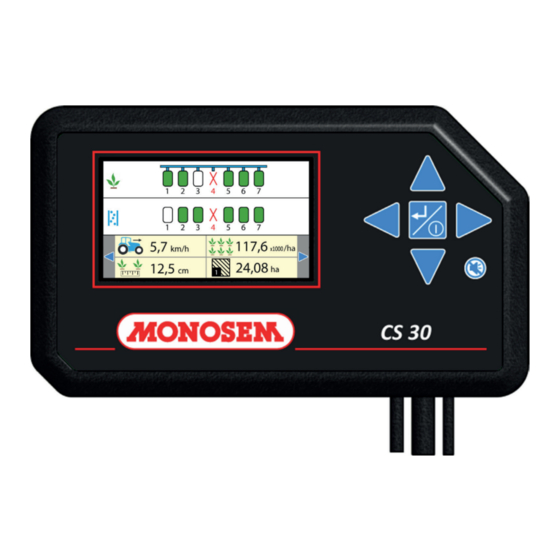
3. DESCRIPTION AND USE OF THE CONSOLE 3. DESCRIZIONE E USO DELLA CONSOLE ① Colour screen. ① Display a colori Description: Descrizione: ② “Down arrow” key. ② Tasto «freccia giù». ③ Key muting an alarm. ③ Tasto che consente di staccare il suono di un allarme. ④... - Page 39 3.2 - Work mode 3.2 - Modo lavoro (Classic version) (Versione Classica) The work mode is the mode in which the controller displays all the Il modo lavoro corrisponde al modo in cui il controllore visualizza tutte information necessary to the user to ensure proper monitoring of the le informazioni necessarie all’utente per garantire un buon monitoraggio ongoing sowing.
- Page 41 3.3 - Work mode 3.3 - Modo lavoro (Comfort and Premium version) (Versione Comfort e Premium) The work mode is the mode in which the controller displays all the Il modo lavoro corrisponde al modo in cui il controllore visualizza tutte information necessary to the user to ensure proper monitoring of the le informazioni necessarie all’utente per svolgere un corretto controllo ongoing sowing.
- Page 43 3.4 - PROGRAMMING MODE 3.4 - MODO PROGRAMMAZIONE (Classic version) (Versione Classica) The programming mode is the mode used to configure the console. Il modo programmazione è il modo di impostazioni della console. Accuracy of the information given by the console in the WORK mode La precisione delle informazioni riportate dalla console in modo LAVORO depends mostly on the programming accuracy.
- Page 45 3.5 - PROGRAMMING MODE 3.5 - MODO PROGRAMMAZIONE (Comfort and Premium version) (Versione Comfort e Premium) The programming mode is the mode used to configure the console (Fig. 1). Il modo programmazione è il modo di impostazioni della console (Fig. 1). Accuracy of the information given by the console in the WORK mode La precisione delle informazioni date dalla console in modo LAVORO depends mostly on the programming accuracy.
- Page 47 3.6 - NUMBER OF ROWS SETTING 3.6 - REGOLAZIONE DEL NUMERO DI FILE This mode is used to select and save the seeder configuration used. Questo modo consente di selezionare e di salvare la configurazione della seminatrice utilizzata. ① - Number of seeder rows. Description: ②...
- Page 49 ① - Access to the advanced cell management menu. ① - Accesso al menù avanzato di gestione delle cellule . Access code:2468. Codice di accesso 2468. ② - Number of beams connected on the seed planter and number of ② - Numero di fasci connessi lato seminatrice e numero di diramazioni a Description: Descrittivo ③...
- Page 51 ► Example of settings for an 8/12 row combination seed planter: ► Esempio di parametrizzazione per una seminatrice mista 8/12 file : ① - In this example, a 12-channel beam is used, but only the 8 channels ① - In questo esempio, si utilizza un fascio a 12 vie, ma si connettono of the active sowing elements (1-2-4-6-7-9-11-12) are connected.
- Page 52 Fig.1 Fig.2 Fig.3...
- Page 53 3.7 - ALARM THRESHOLDS ADJUSTMENT (Fig. 1 and 2) 3.7 - REGOLAZIONI DELLE SOGLIE DI ALLARME (Fig. 1 e 2) The alarm thresholds allow warning the user in case of over- or under Le soglie di allarme consentono di avvertire l’utente quando vi è una -population on a row.
- Page 54 Fig.1 Fig.2 Fig.3...
- Page 55 3.9 - BRIGHTNESS / SOUND (Fig. 1 and 2) 3.9 - LUMINOSITÀ/SUONO (Fig. 1 e 2) ① - Adjustment of terminal brightness. ① - Regolazione della luminosità del terminale. Description: Descrizione: ② - Adjustment of the buzzer volume in case of alarm. ②...
- Page 56 Fig.1 Fig.2 Fig.3 Fig.4...
- Page 57 3.11 - ACCESSORIES 3.11 - ACCESSORI Fig. 1 : Accessory Menu Fig. 1: Menu accessori Fig. 2 : Work screen Fig. 2: Display di lavoro ① - Turbofan rotation control. ① - Controllo della rotazione della turbina. Description : Descrizione: ②...
- Page 59 3.12 - INFO / SERVICE 3.12 - INFORMAZIONI / SERVIZIO The Info/service menu reflects a system status. It gives general Il menu informazioni/servizio riflette lo stato del sistema. Riporta information on the life of the unit, the version of the software and le informazioni generali sulla vita dell’apparecchio, la versione del electronics, and current battery voltage (controller power supply voltage).
- Page 60 Fig.1 Fig.2...
- Page 61 (la costante numerica è quindi fissata ed è memorizzata automaticamente). Although not recommended by MONOSEM, the user can also enter a forward constant directly. In this case, 9993 can be used as a default Benché sconsigliato da MONOSEM, l’utente può inserire anche value in the case of a radar and 295 for a forward sensor on the engine direttamente una costante di avanzamento.
- Page 62 Fig.1 Fig.2 Fig.3 Fig.4...
- Page 63 3.15 - ALLOCATION OF ROW CUTTINGS 3.15 - ATTRIBUZIONE DEGLI ARRESTI DI RANGO (Premium Version) (Versione Premium) This menu allows you to assign the CR30 switches for the cutting on Questo menù permette di attribuire gli interruttori della CR30 con gli the rows: arresti di rango sui ranghi: ①...
- Page 64 Fig.1 PRIOR STATE OF THE ROW PUSH NEW STATE STATO PRECEDENTE DEL RANGO IMPULSIONE NUOVO STATO VOORGAANDE STAAT VAN DE RIJ Impuls NIEUWE STAAT POPRZEDNI STAN RZĘDU NACIŚNIĘCIE NOWY STAN ACTIVE - GREEN LED SHORT Temporarily INACTIVE - ORANGE LED ATTIVO - LED VERDE BREVE Temporaneamente INATTIVO - LED ARANCIONE...
- Page 65 3.16 - USE OF THE CUTTING BAR CR 30 3.16 - USO DELLA BARRA DI ARRESTI CR 30 (Premium Version) (Versione Premium) MANUAL MODE with switches (Fig.1) MODO MANUALE con gli interruttori (Fig.1) The LEDs allow you to view the status of the rows: I LED permettono di visualizzare lo stato dei ranghi: - row activated.
- Page 66 Fig.1 Fig.2 Fig.3...
- Page 67 SEQUENTIAL MODE with buttons (Fig.1). MODO SEQUENZIALE con i pulsanti (Fig.1). An LED allows to visualize if the sequential mode is active or not. Un LED permette di visualizzare se il modo sequenziale è attivo o no. Active sequential mode. Modo sequenziale attivo.
- Page 68 Fig.1 Fig.2 Fig.3 Fig.4 Fig.6 Fig.5 Fig.7...
- Page 69 3.17 - SETTING UP AND USING THE TRAMLINE 3.17 - IMPOSTAZIONE E USO DEL TRAMLINE (Premium Version) (Version Premium) AUTOMATIQUE TRAMLINE MODE MODO TRAMLINE AUTOMATICO Impostazione del modo tramline automatico (Fig.1): Configuration of automatic tramlining mode (Fig.1): 1 - Larghezza della via del polverizzatore. 1 - Width of sprayer track.
- Page 70 Fig. 1 Fig. 2 Fig. 3 Fig. 4 Fig. 6 Fig. 5 Fig. 7...
- Page 71 MANUAL TRAMLINE MODE MODO TRAMLINE MANUALE Setting the manual tramline mode (Fig. 1) : Impostazione del modo tramline manuale (Fig. 1): 1 - Pass number. 1 - Numero del passaggio. 2 - Number of the rows to be cut (4 rows maximum per pass). - Numero dei ranghi da arrestare (4 ranghi al massimo per passaggio).
- Page 73 3.18 - WARNINGS AND ALARMS 3.18 - AVVERTIMENTO E ALLARMI (Classic version) (Versione Classica) 3.18.1 - “Over-population and under-population” 3.18.1 AVVERTIMENTI «Sovrappopolazione WARNINGS sottopopolazione» An over- population or under -population is materialized on the display Una sovrappopolazione o una sottopopolazione si vede nel display dalla by the «...
- Page 75 3.19 - WARNINGS AND ALARMS 3.19 - AVVERTIMENTI E ALLARMI (Comfort and Premium Version) (Versione Comfort e Premium) 3.19.1 - “Over-population and under-population” 3.19.1 AVVERTIMENTI «Sovrappopolazione WARNINGS sottopopolazione» An over- population or under -population is materialized on the display Una sovrappopolazione o una sottopopolazione si vede nel display dalla by the «...
- Page 76 3sec 117,6 12,5 km/h x1000 x1000 24,08 km/h Serial 65040027A3800070B Classic 46:D1:54:29:37:B9:65:95 Comfort 00:00:00:00:00:00:00:00 Premium...
- Page 77 3.20 - Licence purchase 3.20 - Acquisizione della licenza To upgrade your CS30, please provide us with: Al fine di fare evolvere la licenza della vostra CS30, vi preghiamo di comunicarci: - The serial number of the console and the license key currently registered (send a picture of the license screen) - il numero di serie della console e la chiave di licenza attualmente registrata (inviare una fotografia della videata delle licenze)
- Page 78 4 . MAINTENANCE AND TROUBLESHOOTING Your sowing control console is above all an electronic device, which needs to be treated with care. When sowing is completed, it must be stored in a dry place. If the cells are dirty, they should be cleaned with a soft brush. Symptoms Probable cause Solution...
-
Page 79: Maintenzione E Ricerca Guasti
4 . MANUTENZIONE E RICERCA GUASTI La console di controllo di semina è innanzitutto un apparecchio elettronico. Occorre quindi prenderne cura. Alla fine della semina, deve essere conservata in un posto asciutto. Se le cellule sono sporche, devono essere pulite con una spazzola morbida. Sintomi Causa probabile Soluzione... - Page 80 4. ONDERHOUD EN STORINGZOEKEN Het bedieningspaneel van de zaadregelaar is voornamelijk een elektronisch apparaat. Het moet daarom met zorg worden behandeld. Na de zaaiwerkzaamheden moet het worden opgeslagen op een droge plek. Als de cellen vuil zijn, moeten zij worden schoongemaakt met een soepele borstel. Symptomen Mogelijke oorzaak Oplossing...
- Page 81 4 . WYKRYWANIE I USUWANIE USTEREK Twoja konsola sterownika wysiewu jest przede wszystkim urządzeniem elektronicznym, o które należy prawidłowo dbać. Po zakończeniu wysiewu musi być przechowywana w suchym miejscu. Jeżeli fotokomórki są zabrudzone, muszą zostać wyczyszczone na sucho za pomocą miękkiej szczotki. Prawdopodobna Oznaki Rozwiązanie...
-
Page 82: Garanzia
LARGEASSE (RIBOULEAU MONOSEM) per analisi. Una sostituzione con un pezzo nuovo, una riparazione o un saldo creditore sarà definito in caso di accettazione della garanzia. Lo smontaggio e il rimontaggio sono a carico del rivenditore nell’ambito del servizio normale. -
Page 83: Części Zamienne
SPARE PARTS PEZZI DI RICAMBIO ERSATZTEILE CZĘŚCI ZAMIENNE... - Page 84 Faisceau Y 16 rangs 65031060 Rallonge de faisceau 18 rangs 5m 65031065 Rallonge de faisceau 18 rangs 10m 65031068 Faisceau Y 18 rangs betterave châssis repliable 65040027 Contrôleur de semis CS30-18 COMFORT 65040037 Contrôleur de semis CS30-18 CLASSIC 65040035 Kit fixation console MONOSEM...
- Page 85 OPTION COUPURES DE RANG CR30 65040036 65040038 10230452 10230259 10230451 10230453 66008446 64040145 65031022 20084463 64040146 65031023 10500091 64040147 65031024 10590006 64040148 65031025 65031026 Public P04620020 Réf. Réf. Réf. Réf. Désignation Réf. Réf. Réf. Réf. Désignation 10230259 Câble d’alimentation pour boitier gestion de coupure 10230451 Module de gestion de coupure CR 30 10230452...
- Page 86 ENSEMBLE CELLULES POUR CONTRÔLEURS DE SEMIS « DICKEY JOHN » 10230118 10992007 10992033 65031038 10991026 10991025 10991024 65030025 10200169 10200221 65030027 20049850 65030028 10992238 10992322 10992323 10992324 10992082 Public P04500011 Réf. Réf. Réf. Réf. Désignation Réf. Réf. Réf. Réf. Désignation 7263 10200169 Carter plastique de protection cellule NG Plus...
- Page 87 ENSEMBLE CELLULES POUR CONTRÔLEURS TT2 « MONOSEM » 30230433 10200354 10992436 10500001 10200350 65002122 10992436 10200351 10230445 65002113 65030029 P04640012 Réf. Réf. Réf. Réf. Désignation Réf. Réf. Réf. Réf. Désignation 10200350 Carter plastique droit sur couvercle 10200351 Carter plastique gauche sur boitier...
- Page 88 10230260 65035020 65009567 10991099 10230125 65035021 65031062 65031069 10230250 Public P04510010 Réf. Réf. Réf. Réf. Désignation Réf. Réf. Réf. Réf. Désignation 10230125 Câble capteur de vitesse 10230250 Radar « 3 » pour contrôleur de semis 10230260 Capteur de vitesse et rotation DJ 10991099 Capteur de vitesse 65009567...
- Page 89 SUPPORT RADAR TIP & TOP 10603016 10600016 66005207 66008474 10511007 66005398 10620022 10634019 10609046 10634020 10562016 10600010 10620095 10600010 66008322 10600016 10502014 66005399 66007619 30634040 10502024 30512063 66007268 10507076 20072684 20064875 10621044 20064872 10620088 10510097 66007270 20072700 10600010 10603012 10603006 P04010163 Réf.
- Page 90 SUPPORT CAPTEUR DE VITESSE TIP & TOP 10634020 10600016 66003968 10230260 66004169 10620064 10609046 10501054 20042590 10561053 20039670 10629009 20064841 10591909 10600008 10074087 10161007 10561055 10990086 10230061 10591913 20042590 10992348 66004535 10620064 10591909 10512079 10090210 10501054 10230061 10629009 10609024 10603010 10620095 10600008 10090209...
- Page 91 COUPURE DE RANGS TIP & TOP 10230175 10075056 10230100 10200174 10200238 10500061 10603008R 10219004 20049960 65040109 10511058 10159050 10511003 65009363 10160009 10600010 20065981 10601008 10620042 10160034 10174130 10511058 65009362 10075030 10500091 20049910 10075029 10075028 10040074 MONTAGE NC 66004995 10591905 10601010 10219106 20049950 10219092...
- Page 92 SUPPORT CAPTEUR DE VITESSE ET ROTATION 10230366 10230029 10591937 10591937 10230061 10230061 40090262 40090262 30600004 30600004 41047962 41047962 10591932 10591932 10230029 10230366 P0401270 Réf. Réf. Réf. Réf. Désignation Réf. Réf. Réf. Réf. Désignation 10230029 Capteur de vitesse 4878 10230061 Aimant pour capteur de vitesse 10230366 Capteur de rotation avec voyant lumineux 10591932...
- Page 93 20043970 10230224 10990016 65031043 65031044 65029068 P04650010 Réf. Réf. Réf. Réf. Désignation Réf. Réf. Réf. Réf. Désignation 10230224 Cellule engrais 4417 10990016 Collier de serrage Ø38 inox 20043970 Tube Ø35 pour cellule engrais 65029068 Faisceau Y 24 rangs (2x12) 65031043 Faisceau Y 12 rangs (2x6) 65031044 Faisceau Y 16 rangs (2x8)
- Page 94 SUPPORT CAPTEUR D’ÉLÉMENT NG Plus 4 41077335 41077334 30510097 10603006R 65030108 10580067 10629020 30600005 10603010R 30502016 41077331 30502016 10603010R 41077332 10603010R 41077335 41077341 30512028 P06150351 Réf. Réf. Réf. Réf. Désignation Réf. Réf. Réf. Réf. Désignation 10580067 Vis H M5 x 40 inox 10603006R Écrou frein M6 10603010R Écrou frein M10 10629020...
- Page 95 SUPPORT CAPTEUR D’ÉLÉMENT NG Plus M 20077336 10603010R 65030108 10580067 10629020 10179016 30600005 30502016 41077331 10603010R 41077332 10603010R 30512028 P06160121 Réf. Réf. Réf. Réf. Désignation Réf. Réf. Réf. Réf. Désignation 10179016 Anneau élastique Øext. 16 inox 10580067 Vis H M5 x 40 inox 10603010R Écrou frein M10 10629020 Rondelle Ø5 x 12 x 1 inox...
- Page 96 SUPPORT CAPTEUR D’ÉLÉMENT MECA V4 41077335 41077345 30510097 10603006R 10603010R 65030108 10580067 10629020 30600005 30502016 41077331 41077332 P06040162 Réf. Réf. Réf. Réf. Désignation Réf. Réf. Réf. Réf. Désignation 10580067 Vis H M5 x 40 inox 10603006R Écrou frein M6 10603010R Écrou frein M10 10629020 Rondelle Ø5 x 12 x 1 inox 30502016...
- Page 97 SUPPORT CAPTEUR D’ÉLÉMENT NX M 20077339 10603010R 10179016 41077338 30502016 65030108 10629020 30600005 10580067 10603010R 41077332 30502016 41077331 41065982 30600010 30512021 30502018 P06180071 Réf. Réf. Réf. Réf. Désignation Réf. Réf. Réf. Réf. Désignation 10179016 Anneau élastique Øext. 16 inox 10580067 Vis H M5 x 40 inox 10603010R Écrou frein M10 10629020...
- Page 98 NOTES Par soucis d’amélioration continue de notre production, nous nous réservons le droit de modifier sans préavis nos matériels qui, de ce fait, pourront par certains détails être différents de ceux décrits sur cette notice. Photographies non contractuelles.
- Page 100 ... oraz do wszelkich prac spulchniania i okopywania. Skontaktuj się z nami! The cultivators Le zappatrici De hakfrezen Kultywatory RIBOULEAU MONOSEM Revendeur : 12 rue Edmond Ribouleau 79240 LARGEASSE FRANCE Usines Technique Recherche Informations TEL. 05 49 81 50 00...
Need help?
Do you have a question about the CS 30-18 and is the answer not in the manual?
Questions and answers