Table of Contents
Advertisement
Quick Links
Advertisement
Table of Contents

Related Manuals for Canberra Lynx DSA


Summary of Contents for Canberra Lynx DSA
- Page 1 Lynx Digital Signal Analyzer User's Manual 9240227J...
- Page 2 Mirion Technologies, Inc. Mirion Technologies (Canberra), Inc., 800 Research Parkway, Meriden, CT 06450 Tel: 203-238-2351 FAX: 203-235-1347 www.mirion.com. The information in this document describes the product as accurately as possible, but is subject to change without notice.
-
Page 3: Table Of Contents
Editing an MCA's Settings ....................... 27 Editing the Definition ....................... 27 The MCA Input Definition (MID) Editor ..................28 Basic Concepts ......................... 28 Viewing the Current Database ...................... 29 Loading and Unloading Definitions (Load/Unload Definitions) ..........30 Lynx DSA User's Manual - 9240227J... - Page 4 Lynx Setup for Administrators and Users ................... 67 Login ............................69 Common Settings Required During Initial Setup and After a Factory Reset ......70 5. Web-Based Operations ..............71 Accessing the Lynx Web Client User Interface ................72 Lynx DSA User's Manual - 9240227J...
- Page 5 Reboot ............................ 130 Alternate Web Sites ........................130 A. Specifications ................131 Acquisition Device Input ......................131 Acquisition Device Outputs......................134 High Voltage Power Connectors ....................135 Communication Ports ......................... 135 Front Panel Indicators ......................... 136 Lynx DSA User's Manual - 9240227J...
- Page 6 Pileup Rejection With a Live Source ..................189 Live Time Correction With a Live Source ................191 PUR Guard ..........................193 PUR Guard Setup ........................194 PUR Guard Adjustment Using a Live Spectrum ..............195 Lynx DSA User's Manual - 9240227J...
- Page 7 Method 2: Update Firmware via the Boot Loader ..............211 Lynx's Internal Batteries ............214 Lynx Battery Replacement ......................214 J. Installation Consideration ............216 K. FCC Notice ................. 217 L. Disposing of This Equipment ............ 218 Index ....................219 Lynx DSA User's Manual - 9240227J...
- Page 8 Product complies with appropriate current EU directives (Low Voltage & EMC). Product complies with appropriate current Ul / FCC /CSA 61010-1 directives (Low Voltage & EMC). Manufacturer's Address Mirion Technologies (Canberra), Inc. 800 Research Parkway Meriden, CT. 06450 USA Lynx DSA User's Manual - 9240227J...
-
Page 9: Preface
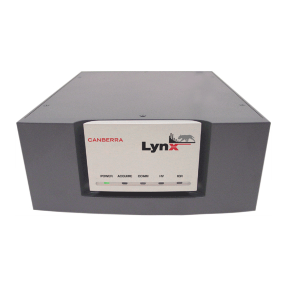
HVPS. This User's Manual is intended for the readers who Figure 1: Front View of Lynx DSA will use the Lynx in their facility to acquire spectroscopic data; the installer or technician who will initially set up the system with other measurement and network equipment;... - Page 10 Notes viii Lynx DSA User's Manual - 9240227J...
-
Page 11: Introduction
For context-sensitive information, simply hover the cursor over the fields you are viewing. About this Manual This manual provides a reference to the capabilities and operation of the Lynx DSA. Each of its chapters covers specific functions. Chapters The Chapters are divided into the following arrangement: Chapter 1, Introduction, is an introduction to the manual’s content and an... -
Page 12: Key Features
Support for virtually all detectors used in gamma, x-ray and alpha • spectroscopy with up to 32K channels of spectral memory. • Dual user interfaces: Lynx DSA User's Manual - 9240227J... - Page 13 Flexible form factor: for Standalone Desktop use; or rack-mount – one Lynx unit, or two Lynx units side by side, may be rack-mounted in 2U of a standard 19 inch electronics cabinet using the optional rack-mount kit. Lynx DSA User's Manual - 9240227J...
-
Page 14: Abbreviations And Acronyms
Universal Serial Bus RNDIS: Remote Network Driver Interface Specification UPnP: Universal Plug and Play URL: Uniform Resource Locator, also referred to as a Web Address UTP: Unshielded Twisted Pair in reference to Ethernet cables Lynx DSA User's Manual - 9240227J... -
Page 15: Acquisition Modes And Acquisition Units
MCS and PHA acquisitions are independent of each other. Spectrum data and elapsed dwell values are stored in persistent memory, meaning that cycling power to the Lynx will abort any acquisition in progress but will not lose data already accumulated. Lynx DSA User's Manual - 9240227J... - Page 16 If data is not requested and buffers run out, eventually new data will be lost. If using List or time-stamped List mode through a custom application, please see important note in Using the Programming Libraries on page 7. Lynx DSA User's Manual - 9240227J...
-
Page 17: Using Programming Libraries
This removed data will then no longer be available to the programming library. Ask your local representative for more information about the Programming Libraries, if required. Lynx DSA User's Manual - 9240227J... -
Page 18: Getting Started
Note: If you wish to access a ‘legacy’ HTML limited version of the site or a Web 2.0 version with Java applets then do one of the following: Lynx DSA User's Manual - 9240227J... - Page 19 If your browser cannot access the Lynx, and your connection to the Lynx is via Ethernet and you followed the procedure in the Communications Setup Appendix starting on page 150, then please stop and contact your Lynx administrator. Lynx DSA User's Manual - 9240227J...
-
Page 20: Introduction To The Lynx Web Client Interface
MCA settings categorized according to their functionality. The Maintenance option in the Navigator view provides access to • maintenance features such as MCA information, errors/diagnostics, firmware updates, etc. Acquisition control is through the Acquisition Panel. • Lynx DSA User's Manual - 9240227J... -
Page 21: Accessing The Lynx System
A simplified menu and sub-menu item reference is provided to guide you along. More detailed discussions on accessing and using the browser-based interface can be found in Web-Based Operation starting on page 71. To begin, access the Lynx, and maximize your Internet browser window. Lynx DSA User's Manual - 9240227J... - Page 22 Web-Based Operation starting on page 71. The Communications Setup Appendix starting on page 150 includes a Quick Setup summary of communication connections, helpful to Network Administrators. Lynx DSA User's Manual - 9240227J...
- Page 23 DHCP server. Click the Save button to save all changes. If the Network Settings have changed, communication to your Lynx will likely stop until your browser is redirected to the new settings. Lynx DSA User's Manual - 9240227J...
- Page 24 General to set acquisition preset times, Acquisition | Coincidence to set coincidence parameters, or Acquisition | External Control to set external control parameters. The Acquisition Mode for Input 1 can be set to PHA, MSS, LIST, and TLIST modes. Lynx DSA User's Manual - 9240227J...
-
Page 25: Sample Energy Calibration
Calibration equation. This option displays the energy calibration coefficients only. These coefficients are used to convert from channel to energy in the spectral plot. A proper calibration can be performed using Mirion’s software like Genie 2000, Apex, or ProSpect. Lynx DSA User's Manual - 9240227J... -
Page 26: Controls And Connectors
HV indicator shows the status of the high voltage power supply. For more information, refer to the Specifications Appendix on page 131. Lynx DSA User's Manual - 9240227J... -
Page 27: Led Status
(i.e., a known limiter was tripped) and the condition no longer exists. A green LED for Incoming Count Rate. Illuminates each time the instrument processes an incoming signal. The intensity of the LED is proportional to the incoming count rate. Lynx DSA User's Manual - 9240227J... -
Page 28: Rear Panel Connectors
Accepts external signals to start/stop data acquisition if using MCS mode; two software selectable modes (one for Start, Stop, or Start & Stop modes; the other for Suspend & Resume mode). MCS CH ADV MCS Channel Advance accepts external MCS channel advance signals. Lynx DSA User's Manual - 9240227J... -
Page 29: General Purpose I/O
A snapshot image of the internally-shaped energy signal for viewing with an external oscilloscope. Selection can be changed through the Web Client's Maintenance | Diagnostics | Monitors option to Off, Slow Shaper, Fast Shaper, and ADC to review the energy signal. Lynx DSA User's Manual - 9240227J... - Page 30 The High Voltage Outputs may be subject to the status and settings for a High Voltage Inhibit signal for a preamplifier. These protective features might be defeated if the Inhibit Signal input is improperly connected or configured. Lynx DSA User's Manual - 9240227J...
-
Page 31: Lynx System Power
Full speed USB Device connection of the Lynx to a host PC; this is a regular USB B-type receptacle. Use a USB A-to-B cable to connect Lynx to your PC. One such cable is provided with the Lynx unit. Lynx DSA User's Manual - 9240227J... -
Page 32: Controls For The Lynx System
If using the Lynx with your Genie 2000 software, you may use your Genie 2000 interface to control your Lynx system. The Lynx DSA provides a thin-client application for setup and control. Please refer to A Brief Overview of the Lynx User Interface on page 8 for accessing the Lynx directly through a web browser. -
Page 33: Factory Reset Control
If the reset button is held pressed for 7 seconds or longer, a Soft Reset • operation will be performed. The POWER Led will blink green as the Lynx re-initializes and switch to solid green when the Lynx is ready. Lynx DSA User's Manual - 9240227J... - Page 34 Lynx must be repeated because the communication settings will have been reset to factory state. Please refer to Lynx Setup for Administrators and Users on page 67 for more information. Lynx DSA User's Manual - 9240227J...
-
Page 35: System Setup
Administrator in order to get the Lynx system configured for your needs. In most cases, communication parameters will be setup once, then remain unchanged until a new change is needed, or a Factory Reset procedure is executed. Lynx DSA User's Manual - 9240227J... -
Page 36: Rack-Mount Option
Note: Most of the information presented in this section is a review of information presented in the Genie 2000 Operations Manual. As it may be relevant, some areas focus on details specific to the Lynx DSA, and some details that are not relevant to Lynx are omitted. -
Page 37: Lynx And Mid Files
If you want to create a very new MCA Definition, the File | New menu command clears the definition table so you can begin a new definition. Because New is a destructive operation, selecting it will cause the program to ask for a confirmation in one of two ways: Lynx DSA User's Manual - 9240227J... -
Page 38: The Mca Input Definition (Mid) Editor
MID file. In addition to using the MID Editor to create a new input definition, it may be used to edit an existing MID file. You may choose to use the MID Editor to change the default settings for some of the Lynx DSA's programmable components. -
Page 39: Viewing The Current Database
To view the current contents of the database, click on the Database menu’s View command. If you click on a line in the list, you can use the Device and Settings menus to look at details of that definition. Click on OK to close the View window. Lynx DSA User's Manual - 9240227J... -
Page 40: Loading And Unloading Definitions (Load/Unload Definitions)
Acquisition and Analysis application can be stored in the database with File | Save. Once saved, the adjustments will be retained in the Input Definition File for future sessions when you Close the data source, or Unload the database. Lynx DSA User's Manual - 9240227J... -
Page 41: Starting The Mid Editor
Note: The phrase “local:Untitled” in the title bar, means that the MID Editor is connected to the local VDM and that no file is currently open; this is the default condition in a non-networked environment. Lynx DSA User's Manual - 9240227J... -
Page 42: Editing An Mca
You can add as many MCAs to the definition as are necessary for your system, highlight each MCA and then click the Add button to add them to the MCA Input Definition Editor list. 5. When you’ve finished adding MCAs, click on the Done button. Lynx DSA User's Manual - 9240227J... -
Page 43: Deleting An Mca
MID file. To begin, click on the Lynx MCA entry in the Definition Table (shown below) that you want to set up. The selection should be highlighted. Figure 10: Selecting the MCA to Set Up Lynx DSA User's Manual - 9240227J... -
Page 44: Interpreting The Definition Entry
UPnP name as it will be required to complete the setup. Refer to the Communications Setup Appendix starting on page 150, as it describes the initial setup and basic operation of the communication interfaces. Lynx DSA User's Manual - 9240227J... - Page 45 Lynx and your Windows PC, the Lynx identification information will be displayed. Select the desired Lynx and click the OK button to automatically fill the IP address information in the Device IP Address field. Lynx DSA User's Manual - 9240227J...
- Page 46 From the Device menu, select the Sample Changer command to display the following dialog box. Figure 14: Sample Changer Selection Choices for the Sample Changer setup are: None • Internal Chgr • GammaAnalyst • • GammaProduct Lynx DSA User's Manual - 9240227J...
-
Page 47: Parameters Settings
Figure 15: Define Input Dialog Input Name The default DETnn name is the name displayed here, allowing you to easily change it to a more meaningful name, such as “H2OSampl”, up to a total of eight characters. Lynx DSA User's Manual - 9240227J... -
Page 48: Saving The Input Definition
In that dialog box, you’ll see a File Descriptor field, which lets you store a 32-character description with your file to make it easier to locate when you want to use it again. Lynx DSA User's Manual - 9240227J... -
Page 49: Changing The Summary View
Note: At any time you can click Next to proceed to the next screen, click Back to return to the previous screen or click Cancel to exit the wizard. You can also access the help topic for each screen by clicking on the Help button. Lynx DSA User's Manual - 9240227J... - Page 50 The device’s IP address or UPnP name will be required to complete the setup. Refer to the Communications Setup Appendix starting on page 150, as it describes the initial setup and basic operation of the communication interfaces. Lynx DSA User's Manual - 9240227J...
- Page 51 Lynx’s IP address, or the Lynx’s exact UPnP Name. See Discovering the Lynx MCA on page 42 for additional information. Figure 17: Configuring the MCA - By IP Address Figure 18: Configuring the MCA - By Name Lynx DSA User's Manual - 9240227J...
- Page 52 Note: Discover will only work on networks that do not block Universal Plug and Play (UPnP) messages and the PC must have UPnP enabled. UPnP in the Lynx is enabled by default. Figure 19: MID Plug and Play Discover of Lynx Lynx DSA User's Manual - 9240227J...
- Page 53 For maximum flexibility at run-time you can set the value here to maximum. Steps 4, 5, and 6 You won’t see the screens for Steps 4, 5, and 6; these steps are not used when setting up a Lynx. Lynx DSA User's Manual - 9240227J...
- Page 54 The Step 7 Mid FileName defaults to UNTITLED, which you’ll probably want to change to something more meaningful. If the name you enter is the same as that of an existing MID file, the system will ask if you want to overwrite the existing file. Lynx DSA User's Manual - 9240227J...
-
Page 55: Lynx Genie 2000 Acquisition Window Adjust
Note that the Adjust screen for a given hardware within the Lynx may actually be composed more than one adjust screen; when additional screens are present, the Next/Prev buttons can be used to navigate them. Lynx DSA User's Manual - 9240227J... -
Page 56: Stabilizer
For best results, the windows should be placed so that a shift in the reference peak reflects a significant change in the count rate through the windows. Lynx DSA User's Manual - 9240227J... - Page 57 The Gain Rate Divider is a factor by which the level of correction applied to the system gain is reduced by. This value in effect determines the aggressiveness of the stabilization algorithm. The algorithm becomes less aggressive as the correction divider is increased. Lynx DSA User's Manual - 9240227J...
-
Page 58: Dsp Gain Parameters
MID Editor or MID Wizard session by selecting MCA Number 1 for PHA or Number 2 for MCS. The DSP Gain settings screen for the Lynx contains the following controls. Figure 23: Adjust Screen’s DSP Gain Settings Lynx DSA User's Manual - 9240227J... - Page 59 For normal operations, this setting should be set to Auto. Please note that in Manual mode the FDisc threshold can be set below the noise level possibly causing wanted data to be rejected. Lynx DSA User's Manual - 9240227J...
- Page 60 TRP Inhibit This setting is in effect when the TRP Inhibit Mode is set to Manual. Sets the TRP Inhibit Time to a value from 0 to 160 μs in steps of 10 μs. Lynx DSA User's Manual - 9240227J...
-
Page 61: High Voltage Parameters
The 200 volts range has a single connector for both positive and negative voltages. Voltage Limit The Voltage limit control establishes the HVPS’s maximum output voltage within the selected range. The Voltage Limit setting must be established before the Voltage control is adjusted. Lynx DSA User's Manual - 9240227J... - Page 62 Select to Disable or Enable the high voltage supply's Inhibit Latch. Default state is Enabled. WARNING: Please note that when HVPS Inhibit is Disabled, the Inhibit Signal cannot shut down the HVPS (i.e. in case of detector warm-up) resulting in possible damage to the detector. Lynx DSA User's Manual - 9240227J...
-
Page 63: Dsp Filter Parameters
Sets the device’s pole/zero setting from 0 to 4095. The values 1 to 4095 represent cancellation οf preamplifier time constants from 1.7 ms to 40 µs respectively; a value of zero sets the pole/zero compensation off (time constant of infinity). Lynx DSA User's Manual - 9240227J... -
Page 64: Sample Changer Parameters
TTL-low signal as “Changer is Ready”. If the “Changer is not Ready” then the start of a PHA or MCS acquisition will be deferred until the “Changer is Ready” condition is met or acquisition is aborted. Lynx DSA User's Manual - 9240227J... - Page 65 Load Sample/Start The Load operation loads the next sample into the sample changer. Sample Num. The Load operation loads the specific sample number specified through the Sample Num setting into the sample changer. Lynx DSA User's Manual - 9240227J...
- Page 66 Stop Issues a stop command. This command stops all sample changer motion. Clear Error Issues a clear error command. This command directs the sample changer to clear all internal hard and soft PLC errors Lynx DSA User's Manual - 9240227J...
-
Page 67: Mcs Parameters
ICR Value reported through the Status page for the selected dwell time. Selecting TTL enables the MCS’s “TTL mode” where all TTL events • received through the rear panel’s MCS input are counted for the selected dwell time. Lynx DSA User's Manual - 9240227J... -
Page 68: Acquisition Setup
The datasource type is defined during the MID Editor or MID Wizard session by selecting MCA Number 1 for PHA or Number 2 for MCS. Figure 30: Acquisition Setup Controls in Genie 2000 for PHA Lynx DSA User's Manual - 9240227J... -
Page 69: Counting Modes
PHA ACQ SS (for PHA) or MCS ACQ SS (for MCS) connector to control the storage of data once the acquisition has been ‘armed’ with a Start acquire command. See “Arming the acquisition” below. Lynx DSA User's Manual - 9240227J... -
Page 70: Input Size
The Computational Presets are mutually exclusive with each other, but any one can be combined with either a live time or real time preset. None Selecting None disables all computational presets. Only the time preset will be used in this case. Lynx DSA User's Manual - 9240227J... -
Page 71: Coincidence
Gate Delay (µs) Selects the time window (µs) available for arrival of the qualifying gate pulse. Recording of the event is delayed until the qualifying signal occurs or the window time expires. Lynx DSA User's Manual - 9240227J... -
Page 72: System Connections For A Detector
Chapter 4 System Setup System Connections for a Detector This describes a basic system consisting of a Lynx, a CANBERRA Germanium Detector and its Preamplifier (or preamp), and a PC running Genie 2000, Apex, or ProSpect. Figure 32: Typical Lynx System Connections with a Detector... -
Page 73: Basic Detector Setup Using Lynx
Lynx's HV+ connector. If your detector requires, and you've configured the Lynx to supply negative • high voltage, connect the SHV cable between the preamp's HV INPUT connector and the Lynx's HV– connector. Lynx DSA User's Manual - 9240227J... -
Page 74: Communicating With Lynx
2. Connect a BNC cable between the preamplifier's HV INH connector and the Lynx's HV INH connector. 3. For a system using CANBERRA's Model 2101 Transistor Reset Preamplifier, connect a BNC cable between the 2101's INHIBIT connector and the Lynx's TRP INH connector. -
Page 75: Lynx Access - Default Settings
The Communications Setup Appendix starting on page 150 describes the initial setup and basic operation of each of these interfaces. In order to access the Lynx DSA for the first time, you must first connect to it (preferably using an Ethernet connection), then configure the selected computer interface to access the Lynx at the appropriate default IP address described above. -
Page 76: Universal Plug And Play
Next, assuming your computer’s Ethernet interface has been configured to access the Lynx at the static IP address: The Lynx DSA is powered up and turned on. The POWER Led on the • Lynx’s front panel is steady green. Your network cable is plugged into the RJ45-type network jack labeled 10/100 Base T on the Lynx’s rear panel. -
Page 77: Communication Interfaces
Lynx will be connected to a network with other devices, in which case the address of each may be dynamically assigned by network’s DHCP server, or must be manually assigned to eliminate address contentions. Lynx DSA User's Manual - 9240227J... - Page 78 Ethernet and therefore emphasized in this document. Establish an Ethernet connection between your computer and the Lynx DSA using the Lynx’s default settings. The simplest and most reliable connection is Ethernet, either direct using crossover cable, or indirect through a network. If needed, the following references contain additional information on establishing such connection: •...
-
Page 79: Login
Lynx Setup for Administrators and Users Login By default, the Login feature on a new Lynx DSA is disabled. If Login had been enabled, then the default Lynx Web Client’s Login page similar to the one shown below would be displayed. -
Page 80: Common Settings Required During Initial Setup And After A Factory Reset
Accessing your Lynx through the UPnP Name on page 14. Factory Reset procedure enables UPnP advertising in the Lynx, and resets the UPnP name to Lynx. UPnP is enabled on a new Lynx received from the factory. Lynx DSA User's Manual - 9240227J... -
Page 81: Web-Based Operations
(default) Powerful, full-capability, and graphics-rich user interface. Supported by practically all browsers. http:// <Lynx address> ‘legacy’ HTML web client Limited functionality including no /main.asp?html5=1 DSO, no time-series plot, no interactive spectrum plot. Lynx DSA User's Manual - 9240227J... -
Page 82: Accessing The Lynx Web Client User Interface
Lynx Web Client User's Manual.pdf located in the Documentation folder of the supplied CD. The figure below shows the Lynx Web Client’s application’s basic views. Figure 38: Data and Navigator Views of the Lynx Web Client Application Lynx DSA User's Manual - 9240227J... - Page 83 Deletes currently active ROI Del or Backspace Control-R Redraw plot Shift Number of ROIs. Displays the number of ROIs that contain the peak cursor. This is helpful in determining whether the cursor is in an overlapped region. Lynx DSA User's Manual - 9240227J...
-
Page 84: Overview Of The Lynx Web Client User Interface
The plot consists of a XY graph with counts on the Y-axis and channel number or energy on the X-axis. Graphics properties such as colors, plot type, units, etc. for the plot can be changed through the Navigator’s Preferences settings. Lynx DSA User's Manual - 9240227J... - Page 85 The rectangle can be resized by moving the hand icon to any side of the rectangle. When it changes color, you can move the hand icon and drag the rectangle’s side to a new height or width. Lynx DSA User's Manual - 9240227J...
- Page 86 Each digital signal waveform is displayed in different colors to distinguish between the multiple traces. The waveform can be printed to a printer, depending on the capabilities of your printer and the Internet browser you have chosen. Lynx DSA User's Manual - 9240227J...
-
Page 87: Information View
Displays the current calibration coefficients in effect used by the spectrum graph to convert X-Axis values from channel numbers to energy when the graph’s X- Units are set to Energy. The type of mathematical model is also shown. Lynx DSA User's Manual - 9240227J... -
Page 88: Acquisition Control Panel
LED. Holding the shift key while double clicking on the LED will clear the fault. Double clicking on any of the LEDs will display its settings in the Navigation Panel to the left. Lynx DSA User's Manual - 9240227J... - Page 89 Pressing “Stop” while in MCS acquisition mode, the Web Client application will request whether to stop immediately by aborting the sweep at the current channel, or wait until the end of the current sweep is reached. Lynx DSA User's Manual - 9240227J...
-
Page 90: Digital Oscilloscope
Located on the top right-corner of the Lynx Web Client Application is the option to enable / disable the digital oscilloscope. Selecting the button to “On” ) will enable the digital oscilloscope main screen as shown in Figure 43. Figure 43: Digital Oscilloscope Main Screen Lynx DSA User's Manual - 9240227J... - Page 91 Resolution is maximum when the Horizontal Scale is set to its minimum setting. Shorter range is useful for close examinations of the signal processing; longer ranges are useful when troubleshooting ground-loop signal noise issues. Lynx DSA User's Manual - 9240227J...
- Page 92 If you select “Continuous”, continuous captures will occur as long as the • selected trigger condition is met. No need to manually “Arm” the capture logic in order to allow it to operate. Lynx DSA User's Manual - 9240227J...
- Page 93 Store – This signal goes high when a pile-up free event is detected in the • slow filter. The event will be stored in the spectrum if the system is acquiring and meets all storage qualifications the user has established including LLD, ULD, Coincidence gating etc. Lynx DSA User's Manual - 9240227J...
-
Page 94: Preferences Options
Common features like font size will affect all graphs. Other features like X-axis units affect only the spectral plot. Changes to these settings will be stored in your local browser cache; this means that resetting or clearing your browser will lose all custom settings. Lynx DSA User's Manual - 9240227J... -
Page 95: Miscellaneous
A faster or slower rate can be selected, however the actual performance relies on the performance of the PC and network. Cursor Follows Mouse, when checked, the cursor movement is synchronized to the • mouse pointer. Lynx DSA User's Manual - 9240227J... -
Page 96: Axes
Custom Units Factor – A multiplication factor for converting from • Channel number to Custom units in the spectral plot. Y-Scale Select the Y-axis scale and labels to be displayed as Logarithm, Linear or Square Root. Default value is Logarithm. Lynx DSA User's Manual - 9240227J... -
Page 97: Colors
Focus Color sets the color for the plot cursor when the expand box obtains focus.. • Background Color sets the background color of the graph. • Gridline Color sets the color of the gridlines. • Lynx DSA User's Manual - 9240227J... -
Page 98: Acquisition Options
PHA value over the full energy range of the input signal. For Input #2, the Input Size represents the number of channels, or sequential bins, into which the time-correlated data (based on the current dwell time) will be stored into. Lynx DSA User's Manual - 9240227J... - Page 99 For Input #2, the Input Size represents the number of channels, or sequential bins, into which the time-correlated data (based on the current dwell time) will be stored into. Preset Options Select from Real time, Live time, or None which disables the Preset Limits fields. Lynx DSA User's Manual - 9240227J...
- Page 100 Available for LIST and TLIST. Clock source for time tagging List data. Internal selects the Lynx built-in 1 MHz clock. External selects an external source supplied through the External Sync input. This field is available when the External Synchronization status is set to “Independent”. Lynx DSA User's Manual - 9240227J...
- Page 101 Timing of the external pulse is controlled by user-supplied logic. The storage of a qualified event can be further delayed by the setting of Gate Delay parameter when the value is greater than the filter shaping. Lynx DSA User's Manual - 9240227J...
- Page 102 Gate Delay (µS) The Gate Delay sets the time window available for arrival of the qualifying gate pulse. Recording of the event is delayed until the qualifying signal occurs or the window time expires. Lynx DSA User's Manual - 9240227J...
- Page 103 Note: In all cases, whether or not External Control has been enabled, once acquisition has been armed, the sample changer’s RDY input must be “ready” for storage to begin, otherwise the start of acquisition will be deferred until the “ready” condition is met. Lynx DSA User's Manual - 9240227J...
- Page 104 (Negative polarity) will disable storage of data. As long as the acquisition remains armed, data storage will depend on the TTL-level as described. Stop command or preset condition will terminate acquisition; once terminated, TTL- level changes on the rear panel connector will have no effect. Lynx DSA User's Manual - 9240227J...
- Page 105 1 microsecond to 999 seconds. Preset Options The only Preset Option (other than None) is the number of sweeps to be acquired. The value is defined by the Preset Sweeps. Lynx DSA User's Manual - 9240227J...
- Page 106 Sweep Mode enables (when ON) the external sweep advance mode. MCS acquisition will wait at the end of the current sweep, and advance to the next sweep when a TTL pulse is received on the SWEEP ADV BNC. Lynx DSA User's Manual - 9240227J...
-
Page 107: Calibration Settings
Stabilizer displays the current spectrum stabilizer settings and provides user • access to its adjustments. Auxiliary Counters configures and controls the auxiliary counters. • External Synchronization configures the external synchronization settings. • Sample Changer displays the internal sample changer interface settings. • Lynx DSA User's Manual - 9240227J... -
Page 108: High Voltage Power Supply Settings
Voltage value can be changed whether the high voltage power supply is On or Off. Reading(V) The Reading is a read-only value reported by the Lynx representing the actual voltage in volts currently present on the rear panel’s SHV connector. The reading is updated dynamically every few seconds. Lynx DSA User's Manual - 9240227J... - Page 109 Please refer to the High Voltage Power Connectors on page 135 for the information on the appropriate SHV output connector. Polarity can only be changed while the high voltage power supply is off. Lynx DSA User's Manual - 9240227J...
- Page 110 If the condition persists, a new Fault will be reasserted shortly after clearing it. In some cases fault indications will remain latched until cleared through the Maintenance | Diagnostics | Status option. Lynx DSA User's Manual - 9240227J...
-
Page 111: Gain Settings
Input #1. Applies to PHA, MSS, DLFC, LIST and TLIST. Value is a signed quantity ranging from -32768 to +32767. This range cannot exceed the current the Input Size setting. Lynx DSA User's Manual - 9240227J... - Page 112 The Polarity setting sets the detector signal polarity for the rear panel’s ENERGY input as Positive or Negative. Typically, the Input Polarity must be set to the polarity of the preamplifier's output. Default is Positive. Lynx DSA User's Manual - 9240227J...
- Page 113 TRP Inhibit (μs) This setting is in effect when the TRP Inhibit Mode is set to Manual. Sets the TRP Inhibit Time to a value from 0 to 160 μs in steps of 10 μs. Lynx DSA User's Manual - 9240227J...
-
Page 114: Digital Filter Settings
Sets the baseline restorer mode. With a setting of Automatic, the baseline restorer is automatically optimized as a function of trapezoid shaping time and count rate. With settings of Soft, Medium and Hard, the baseline restorer is set to fixed rates as selected. Lynx DSA User's Manual - 9240227J... - Page 115 The Rise Time setting ranges from 0.2 to 51.0 µs. Note: Having the ability to independently set the Rise Time and Flat Top allows greater flexibility when optimizing the processing time or shaping for a wide variety of detector applications. Lynx DSA User's Manual - 9240227J...
- Page 116 PUR LTC is On, the pileup rejector and LTC are enabled. Off disables the pileup rejector and LTC. For normal operation this setting should be On. Miscellaneous The Miscellaneous tab displays pole zero and Live-Time settings. Figure 57: Miscellaneous Digital Filter Hardware Settings Lynx DSA User's Manual - 9240227J...
- Page 117 The Incoming Count Rate should be between 300 cps and 20,000 cps with limited number of piled up events. A significant number of the event amplitudes should be from 30% to 100% • of the full scale amplitude of the spectrum. Lynx DSA User's Manual - 9240227J...
- Page 118 The default recovery time in the Lynx is approximately 2.5x the shaping time (Rise + Flat Top). The value specified through the Overload Recovery Extension Time ranges from 0 microseconds to 6,550 microseconds in steps of 10 microseconds. Lynx DSA User's Manual - 9240227J...
-
Page 119: Stabilizer
Stabilizer The Spectrum Stabilizer applies only to PHA spectrums. The stabilizer algorithm in the Lynx DSA is based on similar implementations of spectrum stabilization in other CANBERRA MCA’s, where two user-defined regions of interest or windows are used to monitor the count rate and control the stabilization. - Page 120 User settings for the spectrum stabilizer algorithm include the width of the sampling windows, a centroid channel, the spacing, a reference ratio, and correction divider. The relationship between the windows, spacing, and centroid settings are shown in the figure below. Figure 58: Relationship Between Stabilizer Functions Lynx DSA User's Manual - 9240227J...
- Page 121 Sets the allowable correction range based on detector type. NaI selects +/- 10% of the allowed full scale, Ge selects +/- 1% of the allowed full scale. If the correction exceeds the allowed range an over-range or under-range error will be asserted by the Lynx. Lynx DSA User's Manual - 9240227J...
- Page 122 Manual Ratio setting, and Automatic allows the Lynx to calculate the value automatically when acquisition and stabilization are active. For most typical applications this setting should be set to Automatic. Lynx DSA User's Manual - 9240227J...
- Page 123 1. While acquiring in PHA, adjust the coarse gain, fine gain, detector's high voltage (for NaI), etc. to select the desired energy range for PHA. For best results, the settings should be selected so that the Fine Gain is at or near its mid-range. Lynx DSA User's Manual - 9240227J...
- Page 124 PHA acquire is On, and inactive when PHA acquire is Off. In addition, once the stabilizer is activated, certain parameters that affect the signal storage cannot be changed. Lynx DSA User's Manual - 9240227J...
-
Page 125: Auxiliary Counters
Time Series display. Manual mode is supported only through the Programming Libraries. Preset Limit (mS) The Preset Limit defines the counter’s time interval in milliseconds. Same value applies to both counters. Lynx DSA User's Manual - 9240227J... -
Page 126: External Synchronization Settings
Web Client application through the Time Series plot. Time Series Select “On” to enables or “Off” to disables the plot. External Synchronization Settings Activates the settings for the External Synchronization parameters. Figure 61: External Synchronization Hardware Settings Lynx DSA User's Manual - 9240227J... - Page 127 SYNC input if the external sync has been enabled. If the pulse is not received, the Lynx will assert a timeout fault. Lynx DSA User's Manual - 9240227J...
-
Page 128: Sample Changer Settings
Press the Now button to produce an immediate changer advance pulse on the rear panel’s CHGR ADV connector. Status Indicates the “Ready” or “Not Ready” state of the external input TTL-signal at the rear panel’s CHGR RDY connector. Lynx DSA User's Manual - 9240227J... -
Page 129: Single Channel Analyzers (Sca)
The clock source defines the clock source when external synchronization is enabled (turned on). Internal means that the clock source is the internal 1 µS clock. External means that he clock source is defined by the External Sync input. Lynx DSA User's Manual - 9240227J... -
Page 130: Maintenance Options
Lock/Unlock provides the option to lock / unlock the device. Locking • provides read-write access to the device whereas Unlock provides read-only access. Release Notes option provides an easy way to display the current version’s • release notes. Lynx DSA User's Manual - 9240227J... -
Page 131: Network Settings
The UPnP tab contains the settings for Universal Plug and Play. This tab lets you specify the name that is displayed by UPnP discovery and the number of network hops UPnP messages may be transmitted over. Lynx DSA User's Manual - 9240227J... - Page 132 This feature is enabled from Factory Reset state. Note: Turning the “Enable Web application “OFF” will effectively disable the HTML5 Web Client application and may require Technical Support to re- enable it. Figure 66: WEB Network Settings Lynx DSA User's Manual - 9240227J...
-
Page 133: Diagnostics
Click on the Execute button to clear all faults and errors. Acknowledges and clears the currently latched faults and errors. Persisting faults indicate that the condition causing the fault may not have been resolved, or that service is required. Lynx DSA User's Manual - 9240227J... - Page 134 Any reading that is out of tolerance is highlighted in red. The table is dynamically updated every few seconds. Monitors The Monitors tab displays the various selections for output signal at the rear panel’s MON OUT connector. Figure 69: Monitors Diagnostics Settings Lynx DSA User's Manual - 9240227J...
-
Page 135: Firmware Update
In some cases, more descriptive file naming may be used, however, for such cases appropriate documentation will be supplied. Please refer to Appendix H, Updating Lynx Firmware from Previous Versions to V1.5.x on page 208 for instructions on performing a firmware update. Lynx DSA User's Manual - 9240227J... -
Page 136: Mca Information
FPGA Version: Read-only parameter reports the version of the FPGA • design file. Local Time displays your local computer’s date and time. • System Time displays the Lynx’s date and time. This field is dynamically • updated approximately every 2-3 seconds. Lynx DSA User's Manual - 9240227J... -
Page 137: Print Spectrum
Leaving the Password field blank and then clicking on Update will result in an error message. The Web site login required checkbox is used to enforce logging into the device during application startup. Lynx DSA User's Manual - 9240227J... -
Page 138: Backup And Restore
OK to save the settings as a XML file by default. Note: This is a Web browser specific setting that will download the file where the download’s settings location folder is configured to. Lynx DSA User's Manual - 9240227J... - Page 139 Lynx Reset to Factory Defaults Select the Reset button to reset the Lynx unit to its factory default values. Refer to Factory Reset Control on page 23. Lynx DSA User's Manual - 9240227J...
-
Page 140: Lock/Unlock
Please refer to A Brief Overview of the Lynx User Interface on page 8 for URL’s on accessing the alternate web sites. If automatic login is not enabled then you will be presented with the same login screen for both sites. Lynx DSA User's Manual - 9240227J... -
Page 141: Specifications
HVPS in the event of a detector warmup above its safe operating temperature; polarity is software selectable to match the preamplifier. Positive polarity – For CANBERRA preamplifiers; Enable condition (cold • detector) is an open circuit or active high = +1.2 V to +24 V; Inhibit condition (warm detector) is –24 V to <+1.2 V or ground. - Page 142 No action taken if acquisition was off when first pulse was received. Start and Stop – first pulse received will begins acquisition storage. Second pulse received will stop acquisition. Subsequent pulses will be ignored. Lynx DSA User's Manual - 9240227J...
- Page 143 Sample Changer Ready input connector, BNC. TTL compatible, software selectable logic polarity for active-high or active-low. Active signal allows when a Start Acquire command is received. Inactive signal will defer the start of acquisition until CHANGER READY becomes active. Lynx DSA User's Manual - 9240227J...
-
Page 144: Acquisition Device Outputs
Pulses for ∼150 ms for each sample advance command the instrument receives. Single Channel Analyzer output connector, BNC. Pulses for each event with an energy between the lower and upper level discriminators. Lynx DSA User's Manual - 9240227J... -
Page 145: High Voltage Power Connectors
Port settings under software control and are configurable. Factory settings cooperate with Universal Plug n Play detection by a host Windows computer, and the wired Internet interface is operational out-of- the-box using the static URL 10.0.0.3. Lynx DSA User's Manual - 9240227J... -
Page 146: Front Panel Indicators
(Genie 2000 or the web browser). ACQUIRE Green LED that illuminates Steady On when the instrument is acquiring data. COMM Green LED that illuminates each time the instrument has received a command over any supported communications interface. Lynx DSA User's Manual - 9240227J... -
Page 147: Programmable Controls
Conversion Gain setting. Conversion gain is set automatically through Input Size setting. In PHA, DLFC, and MSS the Input Size also determines the size of the PHA spectrum in channels. Lynx DSA User's Manual - 9240227J... -
Page 148: Digital Filter
33 settings for flat top times from 0 to 3.2 µs in 0.1 µs increments. PUR GUARD Selects Guard Time (GT) multiplier in increments of 1.1, 1.3, 1.5, 1.7, 1.9, 2.1, 2.3, and 2.5 to reject trailing edge pile-up in the event of detector/preamp anomalies. Lynx DSA User's Manual - 9240227J... - Page 149 The default recovery time in the Lynx is approximately 2.5x the shaping time (2x Rise + Flat Top). The value specified through the Overload Recovery Extension Time ranges from 0 microseconds to 6,550 microseconds in steps of 10 microseconds. Lynx DSA User's Manual - 9240227J...
-
Page 150: Mixed Signal Oscilloscope
X-axis. Variable from zero to N, where N is the upper limit dictated by the HORIZONTAL SCALE selection. VERTICAL SCALE Variable attenuation factor, in percentage, ranging from 0.02% to 100% applied during the reconstruction of the analog data for the analog plot. Lynx DSA User's Manual - 9240227J... -
Page 151: Stabilizer
Selection includes following pulses from the DSP: PEAK DETECT, SLOW DISCRIMINATOR, FAST DISCRIMINATOR, BLR GATE, STORE, EXTERNAL GATE IN, REJECT, and [TRP] INHIBIT. Stabilizer RANGE Defines the allowed stabilization range; selections are Ge of 1% of F/S, or NaI for 10% of F/S. Lynx DSA User's Manual - 9240227J... -
Page 152: Sample Changer Control
Read-only parameter that reflects the status or the rear panel’s CHGR RDY input. When a Start Acquire command for PHA or MCS input is received, the start of acquisition storage for that inputs will be deferred until READY=1. Polarity is selectable through READY POLARITY setting. Lynx DSA User's Manual - 9240227J... -
Page 153: Synchronization
SLAVE sets the Lynx to be controlled by an external signal supplied through • the rear panel’s SYNC connector. MASTER A produces an 200 nanosecond pulse on the SYNC output whose • period in milliseconds is set EXTERNAL SYNC PULSE setting. Lynx DSA User's Manual - 9240227J... -
Page 154: Performance
(8K Spectrum). OVERLOAD RECOVERY Recovers to within 1% of full scale output from x1000 overload in 2.5 non overlapped pulse widths at full gain, at any shaping (processing time), and with pole/zero properly set. Lynx DSA User's Manual - 9240227J... -
Page 155: Pileup Rejection/Live Time Correction
Minimum dwell time is 1 microsecond; maximum dwell time is 999 s. PRESET SWEEP COUNTER – 0 to 2 -1 sweeps. Zero implies forever. CONTROL – Internal or External Start/Stop control both with pulse or level control. Lynx DSA User's Manual - 9240227J... - Page 156 Lynx. For TLIST mode, both the energy component and the associated time stamp for each event is recorded by the Lynx using 1.0 µSec or 0.1 µSec clock resolution Lynx DSA User's Manual - 9240227J...
-
Page 157: High Voltage Power Supplies
High Voltage Power Supplies All outputs are current limited and short-circuit protected. HV INHIBIT INPUT – has two modes. POSITIVE POLARITY – For CANBERRA preamplifiers. Enable • condition (cold detector) is an open circuit or active high = +1.2 V to +24 V;... -
Page 158: Physical
3 m (10 ft) CAT 5 Straight-thru UTP Ethernet cable. • 3 m (10 ft) USB A-B cable. • 3 m (10 ft) RS-232 9-pin serial interface cable. • • AC Adapter • AC Line cord Lynx DSA User's Manual - 9240227J... -
Page 159: Environmental
LYNX-SDK – OS independent Software Development Kit. LYNX-MOUNTKIT - Lynx-19 inch Rack Mount Kit; includes mounting hardware, rack handles and a spacer to allow mounting of one or two Lynx units in a cabinet. Lynx DSA User's Manual - 9240227J... -
Page 160: Communications Setup
Lynx User name is administrator, and the default password is password for the Ethernet and the USB connections. In order to access the Lynx DSA for the first time, you must decide on which method of network communication you intend to use. -
Page 161: Quick Ip Setup Summary
'PC-to-Lynx stand-alone system'. This procedure allows you to connect to and operate the Lynx using your PC and a browser, without other network equipment. Use the “crossover” cable for this connection method. Lynx DSA User's Manual - 9240227J... - Page 162 4. Select the General tab or Alternate Configuration tab and then select the "Use the following IP address" option. Enter the following settings: IP = 10.0.0.X (See note below) Subnet = 255.255.255.0 All other entries are blank. 5. Press OK. Lynx DSA User's Manual - 9240227J...
- Page 163 Reply from 10.0.0.3: bytes=32 time<1ms TTL=128 Ping statistics for 10.0.0.3: Packets: Sent = 4, Received = 4, Lost = 0 (0% loss), Approximate round trip times in milli-seconds: Minimum = 0ms, Maximum = 0ms, Average = 0ms C:\> Lynx DSA User's Manual - 9240227J...
- Page 164 Password because the Lynx is shipped from the factory with its login disabled. If needed, defaults are administrator for the User, and password for the Password. 6. When finished with the setups, simply close your Internet browser. Lynx DSA User's Manual - 9240227J...
- Page 165 Lynx is physically disconnected from the PC and connected to the Network via the “straight-through” cable connection. Communication between the PC and Lynx can be re-established after the PC’s Network Adapter is [re]configured to utilize DHCP. See section below. Lynx DSA User's Manual - 9240227J...
- Page 166 1. From the navigator view select Maintenance | Network Settings | UPnP. 2. Select desired Friendly Name, increase the Time-to-Live value if needed, check the [UPnP] Enable checkbox. When done, accept changes by pressing the Save button. Lynx DSA User's Manual - 9240227J...
- Page 167 UPnP discovery, the Lynx’s UPnP discovery has been enabled, and the Lynx is still not visible on the network via its UPnP Friendly Name, then try increasing the TTL value from its current setting. Lynx DSA User's Manual - 9240227J...
- Page 168 4. From the protocol’s Properties dialog select the General Configuration tab. Select the “Obtain an IP Address Automatically” button. Next, press OK to accept this setting, then continue to press OK to accept and exit all setup dialogs. Lynx DSA User's Manual - 9240227J...
-
Page 169: Alternate Setup Connection
RAS. If the connection is successful, the browser should present the opening page. Due to the performance of the RS-232 interface, considerable time may elapse before the opening page is presented. Log In to the Lynx system if requested. Lynx DSA User's Manual - 9240227J... -
Page 170: Recommended Browser Settings
Select the directory you installed the latest version of Java. • Clear all cached information • Restart the browser • Firefox • Tools->Options->Privacy->Content • Enable Java Enable JavaScript • • Tools->Options->Privacy->Cache Use up to 0 • Tools->Options->Privacy->Cookies • Lynx DSA User's Manual - 9240227J... -
Page 171: Universal Plug And Play
1. Press the Start button on Windows 7 and select the Control Panel from the Start menu, or type “Control Panel” in the search bar and press Enter. 2. Select the Network and Sharing Center icon to activate the network information page. Lynx DSA User's Manual - 9240227J... - Page 172 Publication, SSDP Discovery, and UPnP Device Host services are started, that network discovery is allowed to communicate through Windows Firewall, and that other firewalls are not interfering with network discovery. Contact your network administrator if necessary. Lynx DSA User's Manual - 9240227J...
-
Page 173: Setting Up A Usb Connection
Lynx before the USB connection method may be used. These steps use the conventional IP network access for the Lynx administrator. Refer to the Network options in the Lynx Menu for RNDIS features and assignments. Lynx DSA User's Manual - 9240227J... -
Page 174: Rndis And Usb Driver
“RNDIS.zip” will be downloaded. 6. When the driver files have been downloaded, extract them to a known directory (they will be installed on the host computer). 7. Disconnect your PC from the IP network. Lynx DSA User's Manual - 9240227J... -
Page 175: Connect Your Pc To The Lynx Via Usb
Select “Browse my computer for driver software” (actual text may vary slightly between operating systems) and navigate to the Lynx support CD’s “USB” folder directory containing the Lynx USB driver files, then proceed with the installation. Lynx DSA User's Manual - 9240227J... - Page 176 (TCP/IPv4) for Windows 7, and then click on Properties. The Internet Protocol Properties page opens. This sets up the client side (e.g., your PC's end) of the USB connection to some otherwise-unused address. Figure 75: Setting RNDIS Adapter Properties Lynx DSA User's Manual - 9240227J...
- Page 177 The USB connection is not Java-compliant, so the Digital Oscilloscope is not available via USB, and the spectrum display is a not a 'real-time' Java image. This completes the settings and configuration for a USB connection to the Lynx. Lynx DSA User's Manual - 9240227J...
-
Page 178: Verify The Usb Connection
Lynx’s alternate web pages must be accessed through the direct Ethernet connection using the “crossover” cable discussed in earlier steps. The alternate HTML web page in the Lynx are accessed through the following URL: http://10.0.0.3/main.asp?html5=1 Lynx DSA User's Manual - 9240227J... - Page 179 The setup of a RAS account also requires the device’s system name. The default System Name for the Lynx is: Lynx. The Lynx System Name is accessible through the alternate web pages (see above) at Lynx | Setup | System page in the Name field. Lynx DSA User's Manual - 9240227J...
- Page 180 If you already have these settings done, you can connect with your Lynx by double-clicking that Lynx icon; proceed to Step 1 of RS-232 Parameter Settings to continue to the Login screen for the RS-232 settings. Lynx DSA User's Manual - 9240227J...
- Page 181 3. The New Connection Wizard will open. Select its Next button. Figure 78: The New Connection Wizard 4. Select the Set Up an Advanced Connection option. Click Next. Figure 79: Selecting the Network Connection Type Lynx DSA User's Manual - 9240227J...
- Page 182 5. In the next screen, select the Connect Directly to Another Computer option. Click Next. Figure 80: Selecting the Advanced Connection Options 6. In the next screen, select the Guest option. Click Next. Figure 81: Selecting Guest Lynx DSA User's Manual - 9240227J...
- Page 183 7. The System Name for the Lynx was set up previously under the Setup | System. Enter that name, Lynx here. Click Next. Figure 82: Entering the System Name 8. In the next screen, select Communications Cable Between Two Computers. Click Next. Figure 83: Selecting a Device Lynx DSA User's Manual - 9240227J...
- Page 184 9. Now specify that anyone can use the connection and click Next. Figure 84: Making the Connection Available 10. Click Finish to exit the Connection Wizard. Figure 85: Completing the Wizard 11. Continue onto the next section for more RS-232 connection / RAS account settings. Lynx DSA User's Manual - 9240227J...
- Page 185 Figure 86: User Sign-On using RAS 2. Select the Properties button. These Lynx settings for RAS may be changed at Lynx Menu Reminder: Network | RAS tab in the Accounts section, as the User Name and Password entries. Lynx DSA User's Manual - 9240227J...
- Page 186 4. Scroll down the Maximum Speed list to 57600. Click OK. Figure 88: Configuring the Communications Settings 5. Click OK again to return to the Connect Lynx screen. Setup of the RS-232 connection is now complete for the PC side of the connection. Lynx DSA User's Manual - 9240227J...
- Page 187 The Direct Serial Connection to the Lynx is not supported under Windows 7. Please use the Direct Ethernet connection using the “crossover” cable to establish a connection to the Lynx. See Preferred Setup - Wired IP Network on page 151. Lynx DSA User's Manual - 9240227J...
-
Page 188: Setting Up A Modem Connection
Serial Connection Phonebook entry on your Windows PC. 1. On your Windows PC, right-click on the My Network Places desktop icon and then select Properties. You will see the Network Connections page. You will create a new connection definition here. Lynx DSA User's Manual - 9240227J... - Page 189 2. Select the “Create a new connection” link in the “Network Tasks” pane. Figure 90: Create a New Connection from My Network Places 3. The New Connection Wizard will open. Select its Next button. Figure 91: The New Connection Wizard Lynx DSA User's Manual - 9240227J...
- Page 190 4. Select the Connect to the Network at my Workplace option. Click Next. Figure 92: Selecting the Connection Option 5. In the next screen, select Dial-up Connection. Click Next. Figure 93: Selecting the Dial-up Connection Lynx DSA User's Manual - 9240227J...
- Page 191 Figure 95: Entering the Number of the Modem Line 8. If your PC has the “smart card” option, you'll see the screen below. Select the Do Not Use My Smart Card option. Click Next. Lynx DSA User's Manual - 9240227J...
- Page 192 Note: If your computer does not have the “smart card” option, skip this step. Figure 96: Choosing "No Smart Card" 9. Now specify that anyone can use the connection and click Next. Figure 97: Making the Connection Available Lynx DSA User's Manual - 9240227J...
- Page 193 Modem appropriately. Note: Your specific modem parameters may vary slightly, depending on your Make and Model. Consult your modem's documentation for details. 1. The Connect page should be open after finishing the Wizard. Lynx DSA User's Manual - 9240227J...
- Page 194 Reminder: These Lynx settings for RAS may be changed at Lynx Menu Network | RAS tab in the Accounts section, as the User Name and Password entries. Figure 99: Connect to Lynx via Modem Lynx DSA User's Manual - 9240227J...
- Page 195 Properties window will open. Figure 100: Modem Properties with RAS Setup 3. From the General tab, press Configure... and set the Modem options. Click OK to continue. Figure 101: Setting Your Modem Configuration Options Lynx DSA User's Manual - 9240227J...
- Page 196 Lynx Login page on your Terminal. Log In to the Lynx menu to verify successful operation of this connection. The Modem configuration for use with Lynx should now be complete. Lynx DSA User's Manual - 9240227J...
-
Page 197: Installing Firmware On The Lynx Device
The Lynx will also experience at least one or more 'reboot' during this time (depending on how the update is accomplished). Once you have located the firmware update file, copy the file to a local accessible working folder and review the supplied update documentation for specific instructions. Lynx DSA User's Manual - 9240227J... - Page 198 If acquisition was active for SCA's, Counters, List/TList, or MSS, any data in the internal acquisition buffers will be lost once the device resets. Please refer to Updating Lynx Firmware from Previous Versions to V1.5.x.x Appendix on page 208 for detailed update information. Lynx DSA User's Manual - 9240227J...
-
Page 199: Pur/Ltc Operation
Gain Device Adjust screen. Note: The pile up rejector (PUR) and Live time corrector (LTC) operate as an integral system. The LTC On/Off function controls both the PUR and the LTC. Lynx DSA User's Manual - 9240227J... - Page 200 The background reduction and improved sum peak resolution are directly indicative of the Pileup Rejector’s capabilities, since only sum peak pulses which are indeed 100% in coincidence are processed. Figure 103: Comparing Co-57 Spectra w/ PUR On and Off Lynx DSA User's Manual - 9240227J...
-
Page 201: Live Time Correction With A Live Source
Cs at 2 x 661.6 = 1323.2 keV would interfere with the measurement. 1. Connect the Lynx and set it up as described in System Connections for a Detector on page 62. 2. Verify LTC is set ON. 3. Pole/Zero Compensation Lynx DSA User's Manual - 9240227J... - Page 202 11. Set the LTC ON/OFF switch to Off. Repeat steps 4 through 9. Compare the deviation of source “A’s” spectrum when the LTC is ON and the LTC is OFF. Lynx DSA User's Manual - 9240227J...
-
Page 203: Pur Guard
Time setting (2.5x) requires the previous event to fully return to the baseline before subsequent events are accepted. The default Guard Time (1.1x) is minimum and provides optimum performance and maximum throughput for most detector applications. Lynx DSA User's Manual - 9240227J... -
Page 204: Pur Guard Setup
This is shown as time T in the second figure of the previous section. The required guard time is determined by dividing T by the Peaking Time (1.1T Flat Top Lynx DSA User's Manual - 9240227J... -
Page 205: Pur Guard Adjustment Using A Live Spectrum
FWHM of the spectral peaks remain good, reduce the PUR Guard time again to the next lower setting. Repeat this procedure until spectral distortion begins to reappears, then set the PUR Guard time to the next higher setting. Lynx DSA User's Manual - 9240227J... -
Page 206: Methods Of Detector Matching
5. The following steps optimize the discriminator sensitivity to insure the threshold is at its lowest setting, just above the noise level: • Adjust the FDisc Setting to 0%. The ICR LED indicator continuously glows green. Lynx DSA User's Manual - 9240227J... -
Page 207: Baseline Restorer
This can improve performance at extremely high input counting rates or where more control is required to maintain the baseline, such as with some NaI(Tl) scintillation detector systems or detectors which exhibit excessive microphonics. Lynx DSA User's Manual - 9240227J... -
Page 208: Operation With Reset Preamps
If you are using a CANBERRA Model 2101 preamplifier, disable the Reset Delay using these three steps: 1. Remove all signal and power connections from the preamp. -
Page 209: Using The Reset Input And Inhibit Function
Lynx “OR” the external (preamp) inhibit duration, whichever lasts longer. For proper automatic operation set the preamp inhibit time to minimum, or it can override the optimum inhibit time generated by the Lynx. Lynx DSA User's Manual - 9240227J... -
Page 210: Manual Inhibit Mode
Detector/Preamp Operator’s manual for this adjustment. Note that when the Lynx Inhibit Mode is set to “Manual”, the system inhibit duration will be the time interval set by the Lynx Inhibit Setting slider bar “OR” the external (preamp) inhibit duration, whichever lasts longer. Lynx DSA User's Manual - 9240227J... - Page 211 Rise Time set to 5.6 µs, Flat Top set to 0.8 µs, Coarse Gain of x304 [find closest Lynx value] and using a Mirion Model 2101 preamp and Co source. For this example the Inhibit Time should be set to approximately 45 µs. Figure 107: Digital Oscilloscope Waveform Showing Trapezoid Filter Lynx DSA User's Manual - 9240227J...
-
Page 212: Rack-Mounting Your Lynx
CAUTION: If opening the Lynx case (required only if rack mounting two Lynx units) you must exercise care to prevent electro-static discharge into the unit. Lynx DSA User's Manual - 9240227J... -
Page 213: Rack-Mounting A Single Unit
Lynx units) you must exercise care to prevent electro-static discharge into the unit. Figure below shows one possible orientation of the components. Figure 109: Rack Mounting a Single Lynx, Showing the Half-rack Filler Piece Lynx DSA User's Manual - 9240227J... -
Page 214: Rack-Mounting Two Units
You must remove the top cover of only one of the Lynx units. In doing so, take care to prevent electro-static discharge, and while handling the equipment, you should minimize your contact with or near its internal components. Lynx DSA User's Manual - 9240227J... - Page 215 You will use two provided flat-head Phillips screws, provided in the kit, to • attach each of the rack bracket/handles to the side of the joined units. Position the handles to the forward-most holes on the side of the Lynx units. Lynx DSA User's Manual - 9240227J...
- Page 216 Install the joined components in any 2U (3.5 inch) opening into the front of your equipment rack, using your rack's mounting screws. Finally, connect the power, network, antenna and Acquisition device cables as usual. Lynx DSA User's Manual - 9240227J...
-
Page 217: Saving Input Data In Ava, N42, And Cam Formats
In either case press the Save link on the main page to accessing N42 or CAM format. Exported data files are typically located in the user’s default Download folder. Figure 111: Saving the Input Data Lynx DSA User's Manual - 9240227J... -
Page 218: Updating Lynx Firmware From Previous Versions To V1.5.X.x
Firmware Updater utility must be used with EXE file, command line, and -u and - p switches to specify user id and password. Prior to using the utility, it is strongly recommended to stop acquisitions on both inputs, turn off the high voltage, stabilizer, and SCA(s). Lynx DSA User's Manual - 9240227J... -
Page 219: Using Batch File
4. Run FirmwareUpdater.exe with the desired arguments to update the firmware. Please refer to the “LynxFirmwareUpdater.exe and arguments” section below. 5. Wait for the process to complete, and then wait a min or 2 more for Lynx to reboot and initialize. Lynx DSA User's Manual - 9240227J... -
Page 220: Lynxfirmwareupdater.exe And Arguments
The full file path and file name may not have spaces! -a <string>, --address <string> Lynx address --ignore_rest Ignores the rest of the labeled arguments following this flag --version Displays version information and exits. --help Displays usage information and exits. Lynx DSA User's Manual - 9240227J... -
Page 221: Method 2: Update Firmware Via The Boot Loader
Lynx Utils CD’s \TFTP folder and the supplied disk.bin file to the temporary \Tftp working directory. 3. From the \Tftp working directory run tftpd32.exe. 4. Connect to the Lynx via Ethernet assuming default IP address of 10.0.0.3. Lynx DSA User's Manual - 9240227J... - Page 222 (then confirm the next step to erase the device's flash storage.) nand write disk.bin “xxx.xxx.xxx.xxx” (to transfer ° the update to the Lynx's flash storage.) where “xxx.xxx.xxx.xxx” is the IP address of your computer’s network adapter. Lynx DSA User's Manual - 9240227J...
- Page 223 As the procedure for flushing a browser may differ from one browser to another, please consult the appropriate documentation of each unique browser to learn how to flush the cache. Lynx DSA User's Manual - 9240227J...
-
Page 224: Lynx's Internal Batteries
Using the hardware utilities in Genie 2000 or APEX turn off the high voltage. b. Disconnect the unit from the detector, computer / network and power supply. 3. Remove the top and side covers as shown below (12 screws). Lynx DSA User's Manual - 9240227J... - Page 225 4. Remove and replace the battery on the MCA board. 5. Reassemble the unit. 6. Connect to the Lynx and configure the IP address to what it was before (refer to the Communication Setup Appendix starting on page 150 for details). Lynx DSA User's Manual - 9240227J...
-
Page 226: Installation Consideration
Any maintenance should be performed by a qualified Mirion Technologies service representative. Operating Protection Impairment Mirion Technologies (Canberra), Inc. is not liable for any operational malfunctions or personal injuries due to mishandling or unauthorized repair and maintenance not detailed in this manual. -
Page 227: Fcc Notice
Operation of this equipment in a residential area is likely to cause harmful interference in which case the user will be required to correct the interference at his own expense. Lynx DSA User's Manual - 9240227J... -
Page 228: Disposing Of This Equipment
Therefore, following the provisions of COUNCIL DIRECTIVE 2002/96/EC on waste electrical and electronic equipment (WEEE), we ask that you contact your nearest Mirion Technologies office for instructions on the proper disposal of this equipment. Lynx DSA User's Manual - 9240227J... -
Page 229: Index
Input definition report ......36 sampling options ........90 using ............47 Discovering the Lynx ......43, 50 Input settings ..........45 Display preferences ........92 Installing DSP filter settings ........61 firmware ........133, 195 Lynx DSA User's Manual - 9240227J... - Page 230 ......51 high voltage ........59, 106 configuring the MCA ......48 input ..........45, 96 entering the MID file name ..... 52 MCA............43 selecting the MCA ........48 MCS ............65 Lynx DSA User's Manual - 9240227J...
- Page 231 Verifying the USB connection ....176 Viewing diagnostics information ......131 runtime configuration database ....37 Web client interface ........130 alternate connections ....16, 79, 167 enabling ..........130 launching ........... 16, 79 overview ..........18, 82 Lynx DSA User's Manual - 9240227J...
- Page 232 Notes Lynx DSA User's Manual - 9240227J...
- Page 233 ________________________________________________________ Warranty Mirion Technologies (Canberra), Inc. (we, us, our) warrants to the customer (you, your) that for a period of ninety (90) days from the date of shipment, software provided by us in connection with equipment manufactured by us shall operate in accordance with applicable specifications when used with equipment manufactured by us and that the media on which the software is provided shall be free from defects.
- Page 234 Software License LICENSE: Mirion Technologies, Inc. or its affiliates or subsidiaries (the "Company") grants Licensee a limited, non-exclusive license to use the Software listed on the applicable invoice or purchase order, only in object code form, on one computer or virtual machine. Licensee is not permitted to lease, loan, rent, distribute or sublicense the Software or to use the Software in a time-sharing arrangement.
- Page 235 SEVERABILITY: In the event any provision of this License Agreement is found to be invalid, illegal or unenforceable, the validity, legality and enforceability of any of the remaining provisions shall not in any way be affected or impaired and a valid, legal and enforceable provision of similar intent and economic impact shall be substituted therefor.
Need help?
Do you have a question about the Lynx DSA and is the answer not in the manual?
Questions and answers