Table of Contents
Advertisement
Quick Links
Advertisement
Table of Contents

Related Manuals for Canberra 2015A


Summary of Contents for Canberra 2015A
- Page 1 Model 2015A Spectroscopy Amplifier/Timing SCA User’s Manual 9231694B 01/05...
- Page 2 Copyright 2005, Canberra Industries, Inc. All rights reserved. The material in this document, including all information, pictures, graphics and text, is the property of Canberra Industries, Inc. and is protected by U.S. copyright laws and international copyright conventions. Canberra expressly grants the purchaser of this product the right to copy any material in this document for the purchaser’s own use,...
-
Page 3: Table Of Contents
Table of Contents 1. Introduction ......1 Applications ..........2 Low Level α/β... - Page 4 Linearity Check ......... . 26 SCA Operational Checks.
- Page 5 Input/Output ..........39 Controls .
- Page 6 Notes...
-
Page 7: Introduction
(less than 7 microvolts referred to the input at 2 ms shaping). The Model 2015A is further enhanced by the addition of a timing SCA contained in the same package, offering two modes of single channel pulse height (energy) analy- sis. -
Page 8: Applications
Counting System The Canberra LOW BACKGROUND ALPHA/BETA DETECTOR SYSTEM (2200 & 2201) depicts a particular application of the Model 2015A. In this system, two de- tectors are used in anti-coincidence to distinguish true sample events from cosmic or interference radiation associated with the local environment. The system is ideally suited for measuring isotopes such as Po, and so forth. - Page 9 SCA and DISC information being routed by the 2209A to the respective scalers indi- cating alpha and beta events. Both 2015A’s use the DISC output to provide ULD in- formation. However, the WINDOW (∆E) control on the 2015A associated with the cosmic channel is set to 0.00, thus its threshold is equal to that provided by the...
-
Page 10: Controls And Connectors
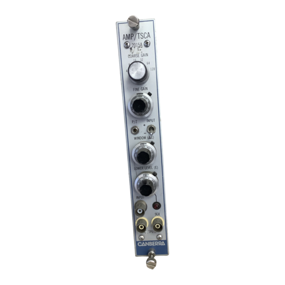
Controls and Connectors 2. Controls and Connectors Front Panel This is a brief description of the 2015A’s front panel controls and connectors. For more detailed information, refer to Appendix A. Figure 2 Front Panel Controls and Connectors... -
Page 11: Rear Panel
Rear Panel Rear Panel This is a brief description of the 2015A’s rear panel connectors. For more detailed in- formation, refer to Appendix A. Figure 3 Rear Panel Connectors... - Page 12 Controls and Connectors Internal Controls Figure 4 Internal Controls...
-
Page 13: Operating Instructions
The purpose of this section is to familiarize you with the operation and controls of the Model 2015A Amplifier/TSCA so that best performance can be obtained. Since it is difficult to determine the exact system configuration in which the module will be used, explicit operating instructions cannot be given. -
Page 14: Performance Adjustments
50% loss will result if the load impedance is 93 ohms. 2. Insert the 2015A into a standard NIM BIN. Preamp power is provided by a 9 pin connector located on the 2015A rear panel. Allow the total system to warm up and stabilize. - Page 15 Spectroscopy System Operation Figure 6 shows the correct setting of the pole/zero control, with Figures 7 and 8 show- ing under and over compensation, respectively for the preamplifier decay time con- stant. Notice some small amplitude signals with long decay times in Figure 6. These are due to charge trapping in the detector and cannot be corrected by the pole/zero control.
- Page 16 Remove all radioactive sources from the vicinity of the detector. e. Set the scope’s channel 1 vertical sensitivity to 5 volts/cm, and adjust the main time base to 0.2 ms/cm. Monitor the 2015A’s AMP OUTPUT and adjust the square wave generator’s amplitude control (attenuator) for output signals of ±...
- Page 17 Spectroscopy System Operation Figure 9 Correct Pole/Zero Compensation Figure 10 Undercompensation Pole/Zero Scope Vertical: 50 mV/cm Horizontal: 0.2 µs/cm Source Square wave pulse and preamp test input. Figure 11 Overcompensation Pole/Zero 3. HPGe detectors and Si Systems with Optical Feedback Preamps. For normal Si Systems, the pole/zero is usually set at ∞...
-
Page 18: Resolution Versus Count Rate And Shaping
Operating Instructions Higher scope sensitivities can also be used, but result in a less precise pole zero adjustment. However, most scopes will overload for a 10 volt input sig- nal when the vertical sensitivity is set for 50 mV/cm. Scope overload will distort the signals recovery to the baseline. - Page 19 Cooled Silicon 8 through 12 The Model 2015A is factory set for 0.5 or 2 µs shaping time constants. However, the shaping time constants can be changed to 8 and 12 µs to be compatible with cooled Silicon detectors. Change the components as follows: 1.
-
Page 20: Resolution Destroying Interfaces
Operating Instructions Figure 13 Internal Shaping Components Resolution Destroying Interfaces 1. Vibration transmitted to the detector and cryostat. This can be through the floor or mounting, as well as direct audio coupling through the air. Vibration isolators in the mounting and sound absorbing covers around the detector can reduce this problem. -
Page 21: Sca Operation
SCA Operation Setup 1. Connect the INPUT of the 2015A to the ATTEN OUTPUT of a reference pulser, such as the Canberra Model 1407. 2. Connect the AMP OUTPUT signal to channel 1 of an oscilloscope. Connect the SCA OUTPUT to channel 2 of an oscilloscope. - Page 22 TSCA 5. Set the 1407 pulser output polarity to POS. Adjust the 1407 pulser PULSE HEIGHT until the 2015A AMP OUTPUT attains an amplitude of 4 volts. 6. Adjust the 2015A pole/zero as outlined in “Performance Adjustments” on page 8.
-
Page 23: Reference Data On Cables
Reference Data on Cables signal, on channel 1 of the oscilloscope, exceeds the LOWER LEVEL (E) plus the WINDOW (∆E) discriminators, a positive logic pulse will appear. Change the DISC A jumper plug back to the LLD position. 12. Change the DISC B jumper plug to the IN position and the LLD jumper plug to the EXT position. - Page 24 Operating Instructions Figure 14 Typical Output Pulse Using a RG58/U Cable RG-62 cable: = 50 ohms source Upper Trace: = 1k ohms load Lower Trace: = 50 ohms load Horizontal = 0.1 µs/cm Scope: Figure 15 Typical Output Pulse Using a RG62/U Cable...
-
Page 25: Preventative Maintenance
The waveforms indicate how important and effective source matching is in eliminating instabilities which cause phenomena such as multiple counting or triggering. For this reason the Model 2015A provides source matched outputs. Figure 16 Typical Output Pulse with a... -
Page 26: Performance Check
Performance Check 4. Performance Check The purpose of this section is for checking the performance of the Model 2015A AMP/TSCA. The checkout will serve to verify that the module is in good operating order. If the Model, 2015A should not meet the performance requirements given in this procedure, it is strongly suggested that the unit be sent back to the factory for cali- bration and/or repair. -
Page 27: Current Measurements
+ 11.99 to + 12.01 V dc –12 D dc – 11.99 to –12.01 V dc Current Measurements Apply power to the 2015A and measure the currents. They should be within the fol- lowing ranges: +24 V dc 40 to 0 mA... -
Page 28: Outputs
400 µs FALL TIME: ATTENUATION: 2. Connect a 93 or 100 ohm terminator to the 2015A rear panel INPUT. 3. Connect the 1407 ATTEN OUTPUT to the 2015A front panel INPUT with RG-62 coax cable. 4. Connect the 1407 NORMAL OUTPUT to the EXT TRIG input of the scope. -
Page 29: Pole/Zero Adjustment
Amplifier Operational Checks 2. Adjust the 1407 PULSE HEIGHT until the AMP OUTPUT amplitude is + 9.9 to +10.1 volts. 3. Place jumper plug J4 in the 93 ohm position. Connect a 93 ohm terminator to the “tee” connector at the scope input. The amplitude of the pulse should be +4.8 to –5.2 volts. -
Page 30: Coarse And Fine Gain Controls
The amplitudes should, reduce proportionately with each COARSE GAIN setting. 5. Set the 2015A CORSE GAIN to 128. 6. Monitor the AMP OUTPUT on the scope and turn the 2015A FINE GAIN control to minimum. The signal amplitude should decrease by approximately 2/3. -
Page 31: Noise Measurement
1407 PULSE HEIGHT until the tail pulse attains an amplitude of 100 mV. 5. Monitor the 2015A AMP OUTPUT on the scope and adjust the pole/zero for no under or overshoots, see Figure 18. Adjust the 2015A FINE GAIN for an OUTPUT pulse amplitude of +9.9 to +10.1 volts. -
Page 32: Linearity Check
Performance Check Linearity Check Integral nonlinearity is a measure, expressed in percentage, of maximum deviation when a straight line is compared to an OUTPUT versus input plot. The OUTPUT is exercised over its full dynamic range. A test for nonlinearity can be conducted using the resistive summing network shown in Figure 20. -
Page 33: Sca Operational Checks
SCA Operational Checks If the SCA section of the 2015A needs to be recalibrated, it is strongly suggested that the unit be sent back to the factory. Setup 1. -
Page 34: Outputs
4. Set the 1407 PULSER FALL TIME to 50 µs, RISE TIME to MIN, ATTEN to X10, and the LINE/OFF/90 Hz switch to 90 Hz. 5. Adjust the 1407 PULSE HEIGHT until the AMP OUTPUT on the 2015A attains an amplitude of approximately 9 volts. -
Page 35: External Lower Level Check
SCA Operational Checks 4. Move the MODE jumper to the SCA position. Adjust the 1407 PULSE HEIGHT for a 2015A AMP OUTPUT of 10 volts. Vary the LOWER LEVEL (E) discriminator; the SCA OUTPUT pulse will move in time as a function of the LOWER LEVEL (E) discriminator;... -
Page 36: Circuit Description
This section of the manual contains a description of the circuitry used in the Model 2015A Amplifier/Timing SCA. Components are referred to by “reference designa- tions” such as Q2, C5, and R10. Throughout the following circuit analysis, refer to the block diagram and circuit schematics located in the drawings section. -
Page 37: Description Of Circuit
Description of Circuit The enable for monostable A7b is generated by the LLD DISCriminator setting flip flop A6b/A6c. At the conclusion of the SCA OUTPUT pulse, flip flop A6b/A6c is cleared via A8a and Ab. If the AMP OUTPUT pulse, exceeds the ULD reference volt- age, its OUTPUT clears timing monostable (A7a) and flip flop A6b/A6c, terminating the SCA OUTPUT pulse cycle. -
Page 38: Input Amplifier K1
Circuit Description Input Amplifier K1 The differentiation network, POLE/ZERO cancellation circuitry and INPUT POLARITY selection are located at the inverting input of K1. The SHAPING switch S3 (sections S1 through S3 and P1 through P3) selects the passive differentiator capac- itors C3, C4, and pole/zero control RV1 sets the degree of pole/zero compensation. -
Page 39: Restorer
SCA Section Diodes D12 and D13 provide short circuit protection. With an improper load con- nected to the OUTPUT, the voltage drop across R71 and R72 forward bias diodes D12 and D13 respectively. For this condition, the respective OUTPUT transistor is by- passed, the OUTPUT current is derived from the op-amp and limited to approximately ±... - Page 40 Circuit Description The OUTPUT of GAIN AMP K2 is ac coupled, through C64, to the fast discriminator A14. The differentiated signal is also attenuated by 2.5 through resistors R126 and R127. If the signal exceeds the fast discriminator threshold, A14 pin 2, its OUTPUT goes to a logic “1"...
-
Page 41: Disc Output
SCA Section When the SCA MODE jumper plug (J6) is in the SCA position the timing monostable (A7a) is now triggered from the LLD discriminator. The SCA OUTPUT will be gener- ated as before, however the timing information is lost. The timing monostable trigger point is now dependent on the AMP OUTPUT signal rise time and LOWER LEVEL (E) discriminator setting. -
Page 42: Window ( E) Threshold Circuits
Circuit Description Window ( E) Threshold Circuits Here the raw +24 volts is used to generate the WINDOW (E) reference voltage. Tran- sistor Q27 is a current source generating a current through the WINDOW (E) control (RV6). Resistors R118, pot RV8, and transistor Q28 are used to bias the current source. -
Page 43: Troubleshooting
Operating Instructions, refer to page 7. 2. Check Associated Equipment. An investigation should be made to ensure that the trouble is not a result of conditions external to the Model 2015A. Check that the equipment used with this instrument is operating correctly. -
Page 44: Component Replacement
All replacement parts should be direct replacements unless it is known that a different component will not adversely affect instrument performance. Many components in the Model 2015A are standard electronic parts available locally. However, all parts can be obtained through Canberra Industries. When ordering replacement parts from Can- berra, include the following information. -
Page 45: Specifications
Inputs A. Specifications Inputs INPUT – Accepts positive or negative linear pulses from associated preamplifier; am- plitude: ±10 V divided by the selected gain, ±12 V maximum; rise time less than shap- ing time constant; decay time constant 30 µs to ∞; Z ≈... -
Page 46: Controls
30 µs to ∞ preamp fall time constant range. INPUT – Toggle switch sets the Model 2015A for the polarity of the incoming preamplifier signal. -
Page 47: Performance
Performance DISC A – Jumper plug sets the rear panel DISC BNC connector to OUTPUT the Lower Level (E) Discriminator or the Upper Level (E + ∆E) discriminator when DISC B is in the OUT position; factory set to ULD. LLD –... -
Page 48: Connectors
Specifications By resetting an internal jumper, the SCA OUTPUT can be used as an SCA referenced to the AMP OUTPUT crossing the LOWER LEVEL (E) discriminator or as a Timing SCA referenced to the leading edge of the amplified preamp signal; shipped in the Timing SCA mode. -
Page 49: Environmental
Environmental NET WEIGHT – 1.1 kg (2.5 lb). SHIPPING WEIGHT – 2.3 kg (5.0 lb). Environmental OPERATING TEMPERATURE - 0 to 50 °C. RELATIVE HUMIDITY - Up to 80%, non-condensing. Tested to the environmental conditions specified by EN 61010, Installation Category I, Pollution Degree 2. -
Page 50: Installation Considerations
• Compliant grounding and safety precautions for any internal power distribution • The use of CE compliant accessories such as fans, UPS, etc. Any repairs or maintenance should be performed by a qualified Canberra service representative. Failure to use exact replacement components, or failure to reassemble the unit as delivered, may affect the unit’s compliance with the specified EU... - Page 51 Canberra (we, us, our) warrants to the customer (you, your) that for a period of ninety (90) days from the date of shipment, software provided by us in connection with equipment manufactured by us shall operate in accordance with applicable specifications when used with equipment manufactured by us and that the media on which the software is provided shall be free from defects.
- Page 52 Benelux/Denmark (32) 2 481 85 30 • Canada 905-660-5373 • Central Europe +43 (0)2230 37000 • France (33) 1 39 48 52 00 • Germany (49) 6142 73820 Japan 81-3-5844-2681 • Russia (7-495) 429-6577 • United Kingdom (44) 1235 838333 • United States (1) 203-238-2351 For other international representative offices, visit our web site: http://www.canberra.com or contact the CANBERRA U.S.A. office. CSP209 1/07 Printed in U.S.A.
- Page 53 30 µs to ∞ preamp fall time constant range. ary time constant; time to peak ≈ 1.75 X shaping time INPUT – Toggle switch sets the Model 2015A for the ■ constant.
- Page 54 ■ ENVIRONMENTAL OPERATING TEMPERATURE – 0 to 50 °C. ■ OPERATING HUMIDITY – 0-80% relative, non- ■ condensing. Meets the environmental conditions specified by EN 61010, Installation Category I, Pollution Degree 2. © 2007 Canberra Industries, Inc. All rights reserved.
Need help?
Do you have a question about the 2015A and is the answer not in the manual?
Questions and answers