Advertisement
Available languages
Available languages
Quick Links
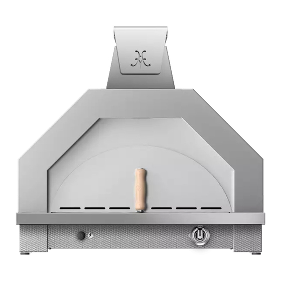
CAMPANIA PIZZA OVEN
IMPORTANT - READ ALL INSTRUCTIONS BEFORE YOU BEGIN.
THE INSTRUCTIONS HEREIN SHOULD BE PERFORMED BY A QUALIFIED SERVICE TECHNICIAN.
THE APPLIANCE MUST BE COMPLETELY COOL AND THE GAS SOURCE MUST BE DISCONNECTED.
CAUTION
Place the pizza oven on a stable countertop or table at a comfortable work height. The appliance is very
heavy (200 lbs / 90 kg) and will require 2 people to lift. Use caution and do not drop the unit - the ceramic
deck material inside the oven may crack.
DURING EXTENDED OPERATION OF THE PIZZA OVEN, THE LIGHT SWITCH BUTTON MAY BE
VERY HOT. USE CAUTION.
TOOLS REQUIRED:
Work gloves
Safety glasses
Phillips screwdriver
2mm Allen wrench
5/16" nut driver or small wrench
7/16" combination or socket wrench
Adjustable wrench
Large pliers
CONTENTS OF KIT AGPO33LK
(for stainless steel units)
LIGHTING
ASSY.
IF YOU PURCHASED THE ABOVE
KIT, START AT DISASSEMBLY STEP
4 AND THEN FOLLOW ONLY THOSE
INSTRUCTIONS WITH AN
COLOR/LIGHTING KIT -
AGPO 33 LK / AGPO 33 LK-XX
Installation Instructions
Some parts inside your Pizza Oven have sharp edges. Care must be taken when
handling the various components to avoid personal injury. Wear gloves when
handling.
WIRE
HARNESS
STRAIN-RELIEF
/ GROMMETS
*
.
CONTENTS OF KIT AGPO33LK-XX
(for painted units with lighting)
INNER
ARCH
LIGHTING
ASSY.
CONTROL
PANEL
IF YOU PURCHASED THE ABOVE
KIT, FOLLOW ALL INSTRUCTIONS.
©2022 Hestan Commercial Corporation
TM
FLUE
COLLAR
FRONT
FRAME
WIRE
HARNESS
STRAIN-RELIEF
/ GROMMETS
1
EN
Advertisement

Related Manuals for hestan AGPO33LK Series


Summary of Contents for hestan AGPO33LK Series
- Page 1 IF YOU PURCHASED THE ABOVE HARNESS KIT, START AT DISASSEMBLY STEP 4 AND THEN FOLLOW ONLY THOSE LIGHTING INSTRUCTIONS WITH AN ASSY. STRAIN-RELIEF / GROMMETS CONTROL PANEL IF YOU PURCHASED THE ABOVE KIT, FOLLOW ALL INSTRUCTIONS. ©2022 Hestan Commercial Corporation...
- Page 2 4. Remove the fasteners shown below. For Stainless Steel units, do this step and proceed to the next step. REMOVE 2 SCREWS LANDING LEDGE REMOVE 2 THUMBSCREWS REMOVE 4 BOLTS USE 10mm OR 7/16” WRENCH CONTROL PANEL REMOVE 2 SCREWS ©2022 Hestan Commercial Corporation...
- Page 3 REMOVE CAP, do this step and proceed BATTERY AND FRAME LOCKNUT to ASSEMBLY step 2. You will not remove the front frame. SPARK IGNITION MODULE (INSIDE) DO NOT PUSH IN !! CONTROL PANEL SPARK MODULE CAP LOCK-NUTS ©2022 Hestan Commercial Corporation...
- Page 4 The lip of the arch goes inward (look at the old assembly you removed in the step above). Install the two INNER screws only. Leave them slightly loose. INNER ARCH INSTALL 2 INNER SCREWS ©2022 Hestan Commercial Corporation...
- Page 5 (shown here in green), until all electrical connections have been completed and tested. Use care when handling the various painted items to avoid scratches during assembly. Do this for stainless WHITE CONNECTOR steel units. FRONT FRAME ROUND LANDING HOLE LEDGE 4 NEW BOLTS LARGE STRAIN RELIEF ©2022 Hestan Commercial Corporation...
- Page 6 (tiny screws on each side of the ceramic bulb holder), or replace the bulb itself with a new G4 “Bi-pin” 20W halogen bulb. You must loosen the screws to replace the bulb. ©2022 Hestan Commercial Corporation...
- Page 7 PUSH IN !! LOCK-NUTS SPARK MODULE CAP WIRING HARNESS Note: If you mistakenly push the spark module inside the oven, you will need to remove the stone retainer, ceramic pizza stones, and stone supports to gain access. ©2022 Hestan Commercial Corporation...
- Page 8 Arrange the cord as shown above. You will tuck the remainder of the cord under the unit so it reaches the back. 7. Re-install the AAA battery (- Negative end goes in first) and spark module cap. Re-install the knob on the gas valve. ©2022 Hestan Commercial Corporation...
- Page 9 A 120VAC - 15 amp GFCI-protected electrical FLUE CAP outlet rated for outdoor exposure will be needed RESTS near the unit for power. The cord length at the ON TOP rear of the unit is approximately 3 ft. [1 m]. ©2022 Hestan Commercial Corporation...
- Page 10 THIS PAGE LEFT INTENTIONALLY BLANK CETTE PAGE LAISSÉE INTENTIONNELLEMENT VIERGE ©2022 Hestan Commercial Corporation...
- Page 11 SI VOUS AVEZ ACHETÉ LE KIT CI- DE CÂBLES DESSUS, COMMENCEZ À L’ÉTAPE 4 ET SUIVEZ UNIQUEMENT CES ENSEMBLE INSTRUCTIONS AVEC UN D'ÉCLAIRAGE PASSE-CÂBLE PANNEAU DE COMMANDE SI VOUS AVEZ ACHETÉ LE KIT CI- DESSUS, SUIVEZ TOUTES LES INSTRUCTIONS. ©2022 Hestan Commercial Corporation...
- Page 12 Pour les unités en Acier Inoxydable, suivez cette étape et passez à l’étape suivante. RETIRER 2 VIS REBORD RETIRER 2 VIS MOLETÉE RETIRER 4 BOULONS UTILISER UN CLÉ DE 10mm OU 7/16po PANNEAU DE COMMANDE RETIRER 2 VIS ©2022 Hestan Commercial Corporation...
-
Page 13: Panneau De Commande
Pour les unités en Acier Inoxydable, effectuez cette étape et passez à l’étape 2 de l’ASSEMBLAGE. Vous ne retirerez pas le cadre avant. MODULE D'ALLUMAGE (À L'INTÉRIEUR) NE PAS POUSSER !! PANNEAU DE COMMANDE BOUTON ÉTINCELANT CONTRE-ÉCROUS ©2022 Hestan Commercial Corporation... - Page 14 La lèvre de l’arche va vers l’intérieur (regardez l’ancien assemblage que vous avez retiré à l’étape ci-dessus). Installez les deux vis INTÉRIEURES uniquement. Laissez-les légèrement lâches. L’ARCH INTERIEUR LÈVRE INSTALLER 2 VIS INTERNES ©2022 Hestan Commercial Corporation...
-
Page 15: Cordon D'alimentation
Soyez prudent lors de la manipulation des différents éléments peints pour éviter les rayures lors du montage. CONNECTEUR BLANC Procédez ainsi pour CADRE AVANT les unités en Acier Inoxydable. TROU ROND REBORD 4 BOULONS BRIDE DE NEUFS CÂBLAGE GRANDE ©2022 Hestan Commercial Corporation... - Page 16 (minuscules vis de chaque côté du support d’ampoule en céramique), ou remplacez l’ampoule elle-même par une nouvelle ampoule halogène G4 «Bi-pin» 20W. Vous devez desserrer les vis pour remplacer l’ampoule. ©2022 Hestan Commercial Corporation...
- Page 17 ÉLECTRIQUE Remarque: Si vous poussez par erreur le module d’allumage à l’intérieur du four, vous devrez retirer le retenue de pierre, les pierres à pizza en céramique et les supports de pierre afin d’y avoir accès. ©2022 Hestan Commercial Corporation...
- Page 18 Vous placerez le reste du cordon sous l’appareil afin qu’il atteigne l’arrière. 7. Réinstallez la pile AAA (- l’extrémité négative entre en premier) et le chapeau du module d’allumage. Réinstallez le bouton sur la robinet de gaz. ©2022 Hestan Commercial Corporation...
- Page 19 GFCI et conçue pour une exposition CHAPEAU DE CHEMINÉE à l’extérieur, sera nécessaire près de l’unité pour REPOSE SUR l’alimentation. La longueur du cordon à l’arrière LE HAUT de l’appareil est d’environ 3 pieds [1 m]. ©2022 Hestan Commercial Corporation...
- Page 20 Hestan Commercial Corporation 3375 E. La Palma Ave. Anaheim, CA 92806 (888) 905-7463 ©2022 Hestan Commercial Corporation P/N 035951 REV B...
Need help?
Do you have a question about the AGPO33LK Series and is the answer not in the manual?
Questions and answers