Table of Contents
Advertisement
Quick Links
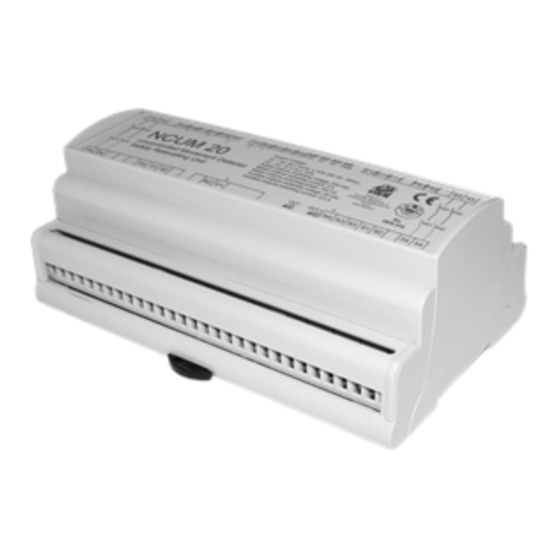
Operating instructions for safety control unit mod. NCUM 20
DESCRIPTION
The unit NCUM20 is a safety device used to detect the uncontrolled movement
of elevators in accordance with EN 81-20:2014, EN 81-50:2014. The operation
of this module is based on the use of guided safety relay contacts.
!
SAFETY PRECAUTIONS
The inputs of the unit(C11-C12-S41-S42) must be safety contacts comply
with paragraph 5.11.2 of the standards EN 81-20:2014 and perform a
function of personal protection; they should not be bypassed (by shorting the
contacts), moved, removed or rendered ineffective by other means. Incorrect
installation or manipulation can cause serious personal injury. The
manufacturer or installer of the machine is responsible for the proper and
safe operation.
The auxiliary output 31-32-33/61-62-63 provides a indication on the status of
the device, so it must not be used in any way as a safety output.
The NCUM20 is not suitable for operation in the presence of ionizing and non
ionizing radiation (X-rays, microwaves, lasers, ultraviolet rays).
The NCUM20 control unit must be assembled in a suitable operating area
(switch cabinet, protective housing).
In the following cases you must use a IP54 cabinet:
- If the safety UCM outputs (13-14,23-24) have a voltage difference between
them greater than 160V
- if outputs of the leveling safety output (43-44, 53-54) have a difference of
voltage between them exceeding 160V
OPERATION
The safety unit NCUM20 integrates the unit for uncontrolled movement and a
leveling control unit. It can be used in different way
Mode with independent leveling (Fig.1): in some application is needed to
separate the elevator levelling from the UCM detector to avoid, in case of exit
from leveling zone, that the controller put the elevator out of order.
In this case, the system needs to add to the NCUM20, also a control unit for the
leveling (NC80,NC96LIFT) with an additional 2 contacts sensor.
The leveling unit output, in parallel with the safety door contact, make the
optoisolated input C11 The magnet used to activate the double contacts sensor
wired on the inputs S11-S12, S21-S22 must be positioned so that its activation
will be longer then the activation of the leveling control unit sensors
If the input PS2 is connected before the car door contact, the NCUM will
automatic restart closing its outputs (13-14/ 23-24) in case a safety contact before
the door has been opened ( it's not an unintended car movement) . If the power
supply sense (PS2) is not used, the door contact has to be wired at the
beginning of the elevator safety circuit.
Mode with or without leveling on the elevator safety circuit (Fig.2): the control
unit NCUM20 integrated as well the leveling function as the uncontrolled
movement function.
The safety door contact is wired in parallel with the outputs 53-54 in case it is
needed the leveling with open doors, and it is connected to the optoisolated input
C11 If the leveling is not necessary the outputs 43-44 must be wired on the input
S41.
If the input PS2 is connected before the car door contact, the NCUM will
automatic restart closing its outputs (13-14/ 23-24) in case a safety contact before
the door has been opened ( it's not an unintended car movement) . If the power
supply sense (PS2) is not used, the door contact has to be wired at the
beginning of the elevator safety circuit.
Mode independent inputs (Fig.3): in this case the system is completely
independent from the elevator safety circuit, in fact it is used the input S42
provided by a second safety door contact(mechanical or provided from the Stem
IP67 Unit) while at the input S41 is connected the output 43-44 of the leveling unit.
The 53-54 can be used as standard leveling output
The unit NCUM20 monitors the signal status of the inputs (C11-C12, S41-S41)
and if a dangerous event happen, it will open the safety outputs 13-14/ 23-24
The unit NCUM20 allows the leveling operation with open doors. Monitoring inputs
S11-S12 and S21-S22it will open the safety contacts 43-44/53-54 if the car
moving out the doors zone(detail on the leveling operation in fig.7 and fig.8)
Hazardous event
Is consider an Hazardous event a car movement with the doors open out of the
door zone. Therefore the positioning of the magnet for the leveling must be due to
guarantee the car stop within one meter in case of uncontroled movement
as indicated in the normative.
Start
As required by law, if a hazardous event occurs, the output will remain open until
the safe operation by a competent person will bring the system in safety
conditions and send a signal to start contacts (S31-S32). If a temporary lack of
power supply happen, the module will continue to work if it is connected to the
battery.
STEM S.r.l. via della Meccanica, 2 I-27010 Cura Carpignano Pavia Italia Tel. +39 0382 583011 Fax +39 0382 583058
!
If the elevator car is at the floor, the safety output (13-14, 23-24) remain
closed instead, if the cabin is out the floor, the level unit is open and in
cosequence also the safety outputs (13-14, 23-24) will be open.
The unit sense the presence of power supply, thanks the inputs PS1,PS2
and it will send an automatic start to close the outputs contact.
STOPPING DEVICES
The stopping elements usable with our device are: electrical brakes,
solenoid lock to activate the overspeed governor, solenoid valves.
The stopping elements have to comply the EN 81-20:2014. If the
switching current to energize the braking element is greater than 3A (6A
in case of outputs 13-14/23-24 connected in parallel) appropriate
contactors in accordance to the point 5.11.2 of the EN 81-20:2014, have
to be installed between NCUM and the coil of the braking elements. The
response time of the contactors have to be considered in the global
system response time calculation.
ASSEMBLY
Installation must be performed by authorized personnel only.
The unit is installed by clipping it to a standard 35 mm top-hat rail.
ELECTRICAL CONNECTION
Electrical connection must be performed by authorized personnel only.
All the electrical inputs must either be isolated from the mains supply by
a separate coils safety transformer in accordance with EN IEC 61558-2-6
with limited output voltage in the event of a defect or by another
equivalent movable mechanism.
Each safety relay output (13-14/23-24/43-44/5354) has a maximum
current of 3 A; the supply connected to the outputs must be protected
from overcurrents by devices adequate to the loads that have to be
protected.
All the output contacts must have an adequate protective circuit for
capacitive and inductive loads. A fast-blow 500mA fuse must be
connected to input A3 of the battery (+12 V).
If a common power supply is used, all the inductive and capacitive loads
(e.g. relay contactors) connected to the power supply must be connected
to appropriate interference suppressors.
SERVICE AND INSPECTION
The correct functioning of the NCUM20 safety unit must be controlled by the
operator and/or by the control circuit of the elevator periodically by checking:
- correct switching function
- secure mounting of components
- correct connection fixing.
The monitoring function of the unit is done at every switching.
In the event of damage or wear and tear, the damaged system component
must be replaced.
Liability coverage is void under the following circumstances:
- if instructions are not followed
- non-compliance with safety regulations
- installation and electrical connection not performed by authorized personnel
- non-implementation of functional checks.
SETUP
If the control unit does not appear to function when operating voltage is
applied (green "Power" LED does not light up), the unit must be returned
unopened to the manufacturer.
Check whether the safety outputs are being switched (see LED display) by
activating the two inputs and START.
Function
Power supply
Second door contact*: CLOSED
Output 13-14 e 23-24: CLOSED
Levelling Sensor S1
Levelling Sensor S2
Output 43-44 e 53-54: CLOSED
*
Second contact of a double door contacts or second output of the
STEM IP67 safety door system.
If the contacts S41 and S42 are bothclosed (+12 V),
the CP LED remains off.
- 1 -
- Original instructions -
LED Table
LED
Color
State
PWR
Green
on
CP
Green
on
OUT
Green
on
on
S1
Green
on
S2
Green
on
OUTL
Green
www.stemsrl.it
stem@stemsrl.it
Advertisement
Table of Contents

Related Manuals for Stem NCUM 20


Summary of Contents for Stem NCUM 20
- Page 1 CP LED remains off. battery. - 1 - STEM S.r.l. via della Meccanica, 2 I-27010 Cura Carpignano Pavia Italia Tel. +39 0382 583011 Fax +39 0382 583058 www.stemsrl.it stem@stemsrl.it...
- Page 2 12 V dc Signal output Signal output 63 61 33 31 FIG. 3 Indipendent safety chain mode - 2 - STEM S.r.l. via della Meccanica, 2 I-27010 Cura Carpignano Pavia Italia Tel. +39 0382 583011 Fax +39 0382 583058 www.stemsrl.it stem@stemsrl.it...
- Page 3 12 V dc 8) Measure the braking trip distance 14 24 33 31 63 61 FIG. 6 Uncontrolled mouvement test STEM S.r.l. via della Meccanica, 2 I-27010 Cura Carpignano Pavia Italia Tel. +39 0382 583011 Fax +39 0382 583058 www.stemsrl.it stem@stemsrl.it...
- Page 4 - The leveling of safety outputs (43-44, 53-54) have a voltage difference between them of less than 160V SAFETY CIRCUIT ORDERING CODE VOLTAGE NCUM20000024 NCUM20000048 NCUM20000060 110V NCUM20000110 220V NCUM20000220 - 4 - STEM S.r.l. via della Meccanica, 2 I-27010 Cura Carpignano Pavia Italia Tel. +39 0382 583011 Fax +39 0382 583058 www.stemsrl.it stem@stemsrl.it...
Need help?
Do you have a question about the NCUM 20 and is the answer not in the manual?
Questions and answers