Advertisement
Quick Links
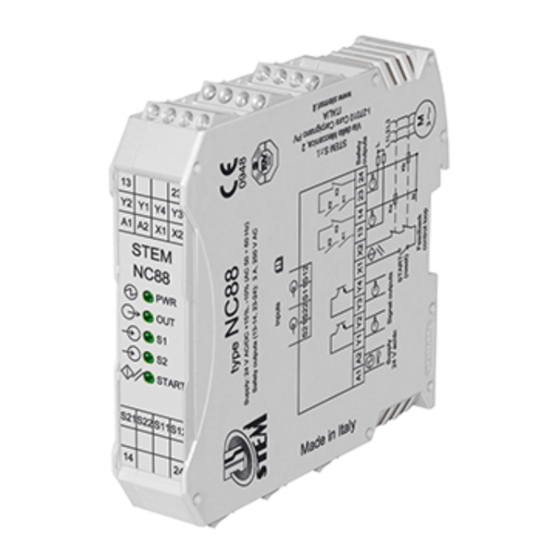
Operating instructions for safety control unit mod. NC8 8
Description
The NC88 safety relay is created for use in safety circuit intended by
EN 81-20:2014, EN 81-50:2014
This module is based upon the use of guided-contact safety relays.
!
!
Safety Precautions
The manufacturer of a machine or installation is responsible for correct and
safe overall function.
Auxiliary output Y1/Y2 and Y2Y3 are optoinsulated and gives informations
about the state of the device; it must not be used as a safety output.
NC88 is not proper for the operation in presence of ionizing and not ionizing
radiations (rays X, microwaves, laser, ultraviolet rays)
(CEI EN 60204-1:2006, §4.4.7).
Functioning
The NC88 Module can control the state of two Reed magnetic sensors : the
output is activated by pressing the START button only if the contacts of two
sensors are closed. The opening of even only one input contact (S1 and/or S2),
leads to a safety situation, by putting the safety outputs in open state and by
preventing the closing even after the re-closing of the contact and the pressure of
the START button.
For automatic start, see connection diagram.
Input channels work on opposite potentials (S11
It's available an input (X1-X2) for feedback with contactors or external relays (see
Ka and Kb on the connection diagram).
The control unit has a dedicated circuit to guarantee the its correct functionality
in case of short voltage dips
The safety is ensured by using guided contacts, by the redundance and by the
interconnection schematic of the contacts.
The responsibility to choose the adequate components for safety applications, for
example guided contacts safety relays, falls to the user.
Assembly
Installation must be performed by authorized personnel only.
The NC88 control unit must be assembled in a suitable operating area (switch
cabinet, protective housing).
The unit is installed by clipping it to a standard 35 mm top-hat rail.
Connections
Inputs(Reed sensors)
S21
A1 A2 Y1
Y2
Y3 Y4
Power supply
24 V ac/dc
Signal outputs
button
(reset)
STEM S.r.l. via della Meccanica, 2 I-27010 Cura Carpignano Pavia Italia Tel. +39 0382 583011 Fax +39 0382 583058
-
+
; S21
).
+
-
S2
S1
S22
S11S12
K2
K2
K3
K3
K3
K1
K1
X1
X2 13 14
23
24
Ka
Start
Kb
N
Feedback
control loop
Electrical Connection
Electrical connection must be performed by authorized personnel only.
All the electrical inputs must either be isolated from the mains supply by a
separate coils safety transformer in accordance with EN IEC 61558-2-6
with limited output voltage in the event of a defect or by another equivalent
movable mechanism.
The outputs of the relays have a maximum current of 3 A; the supply
connectedto the outputs must be protected from overcurrents by devices
adequate to the loads that have to be protected.
All the output contacts must have an adequate protective circuit for capacitive
and inductive loads.
If a common power supply is used, all the inductive and capacitive loads (e.g.
relay contactors) connected to the power supply must be connected to
appropriate interference suppressors.
Service and Inspection
The correct functioning of the NC88 safety unit must be controlled by the
operator and/or by the control circuit of the elevator in which it is used
periodically, by checking:
- Correct switching function of each sensor by checking:
a) that the opening of the single sensor will cause the opening of the safety
outputs (13-14 / 23-24)
b) that the closure of the same sensor will cause the closing of the safety
outputs (13-14 / 23-24) as a result of a startup command
- secure mounting of components
- correct connection fixing.
The monitoring function of the unit is done at every switching cycle. If the
elevator is in a door zone and following the eventual start command, the
safety device does not activate its safety outputs, do not turn off and turn on
the device, then proceed to the checking of the possible sensor fault and
perform the above tests in point a) and b).
In the event of damage or wear and tear, the damaged system component
must be replaced.
Liability coverage is void under the following circumstances:
- if instructions are not followed
- non-compliance with safety regulations
- installation and electrical connection not performed by authorized personnel
- non-implementation of functional checks.
Setup
If the control unit does not appear to function when operating voltage is
applied (yellow LED does not light up), the unit must be returned unopened to
the manufacturer.
Check whether the safety outputs are being switched (see LED display) by
activating the two inputs S1, S2 and START.
Automatic start connections
1) Automatic start with the sync time between inputs infinite
(ONLY for use in the lift industry - EN81-20: 2014).
Reed switch sensors ID, IS and IZ.
In this configuration the inputs synchronization time among the closing of IZ
and one between IS and ID, it is endless, but a correct closing sequence has
to be respected: the first contact to be closed is IZ, then IS or ID.
This configuration cannot be used with Hall effect sensors.
Safety
outputs
L
IZ
L1L2
L3
S11
S12
S21
GND
+
M
2) Short-circuit of S33 and S34; in this case there will be a
3
synchronism time between inputs of 600 ms.
MD
MZ
MS
ID
IS
IZ
IS
ID
Feedback loop of the
external contactor
(short-circuit if not used)
S22
X1 X2
NOT CONNECTED
+
www.stemsrl.it
stem@stemsrl.it
X1 X2
Advertisement

Related Manuals for Stem NC88


Summary of Contents for Stem NC88
- Page 1 2) Short-circuit of S33 and S34; in this case there will be a X1 X2 synchronism time between inputs of 600 ms. STEM S.r.l. via della Meccanica, 2 I-27010 Cura Carpignano Pavia Italia Tel. +39 0382 583011 Fax +39 0382 583058 www.stemsrl.it stem@stemsrl.it...
- Page 2 EN12015, EN12016, EN 61000-6-2, EN 61000-6-3, EN 55011:1999 In accordance with EN 81-20:2014, EN 81-50:2014 Approvals TÜV n° EDES 007 STEM S.r.l. via della Meccanica, 2 I-27010 Cura Carpignano Pavia Italia Tel. +39 0382 583011 Fax +39 0382 583058 www.stemsrl.it stem@stemsrl.it...
Need help?
Do you have a question about the NC88 and is the answer not in the manual?
Questions and answers