Table of Contents
Advertisement
Quick Links
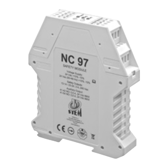
Operating instructions for safety control unit mod. NC97
Description
The NC97 safety relay is created for use in safety circuit intended by
EN 60204-1, EN ISO 13849-1, EN ISO 13850, EN ISO 14119:2013.
This module is based upon the use of guided-contact safety relays.
Safety Precautions
!
!
Safety switches fullfills a personal protection function; they must not be bypassed
(bridging the contacts), moved, removed or otherwise made ineffective. Incorrect
installation or manipulation can lead to severe injuries to personnel. The
manufacturer or the technician that intall the machinery is responsible for correct
and safe overall function.
Auxiliary output 41/42/54 gives informations about the state of the device; it must
not be used as a safety output.
The NC97 is not proper for the operation in presence of ionizing and not ionizing
radiations (rays X, microwaves, laser, ultraviolet rays)
(EN 60204-1, §4.4.7).
Functioning
The NC97 Module can control the state of two contacts (safety Reed sensors,
emergency stop button, mechanical safety switches, interlocks for mobile guards): the
output is activated by pressing and releasing the START button only if the contacts of
two sensors are closed. The opening of even only one input contact, leads to a safety
situation, by putting the safety outputs in open state and by preventing the closing
even after the re-closing of the contact and the pressure of the START button.
If the NC97 is used to control emergency stop button, after the intervention of the
device, the reset of the command shall not restart the machinery but only permit
restarting (EN 60204-1, §9.2.3.4.2, EN ISO 13850, §4.1.4).
If the NC97 is used to control interlocks for mobile guards, the reclosing or resetting
of an interlock safeguard shall not initiate hazardous machine operation
(EN 60204-1, §9.3.1).
Shorting terminals Y1-Y2-X1, the restart of the device is automatic (in this case A2
has not to be connected to start circuit); the behavior of the machinery to the restart
of the device - or the not automatic restart of the dangerous elements of the
machinery - depends on the realization of the command circuit of the machinery
according to the risk evaluation effected by the user.
If the emergency stop command has only one N.C. contact, it must be connected
between the positive supply contact (L+) and the A1 contact; if no safety sensors are
connected to the unit, S11-S12 and S21-S22 have to be bridged .
Safety category 4 is granted only if (see connection diagram):
- to interrupt the load are used two relays, each connected to an input of
the safety unit;
- the NC auxiliary contacts of the relays controlled by the control unit (Ka, Kb)
are inserted in the feedback loop.
The safety is ensured by using guided contacts, by the redundance and by the
interconnection schematic of the contacts.
The responsibility to choose the adequate components for safety applications, for
example guided contacts safety relays, falls to the user.
Electrical Connection
Electrical connection must be performed by authorized personnel only following the
indications of EN ISO 13849-1 and EN ISO 13849-2.
All the electrical inputs must either be isolated from the mains supply by a separate
coils safety transformer in accordance with EN IEC 61558-2-6 with limited output
voltage in the event of a defect or by another equivalent movable mechanism.
The supply have to be connected in a permanently way and using a cable with a
maximum lenght of 10 m; the sonsors have to be connected to the unit using cables
with a maximunum lenght of 30 m.
The outputs of the relays have a maximum current of 3 A; the supply connected to
the outputs must be protected from overcurrents by devices adequate to the loads
that have to be protected.
All the output contacts must have an adequate protective circuit for capacitive and
inductive loads.
All the inductive and capacitive loads connected to the power supply must be
connected to appropriate interference suppressors.
Assembly
Installation must be performed by authorized personnel only.
The NC97 control unit must be assembled in a suitable operating area (switch
cabinet, protective housing, at least IP 54) and installed by clipping it to a standard
35 mm top-hat rail.
Setup
If the control unit does not appear to function when operating voltage is applied
(green "Power" LED does not light up), it must be returned unopened to the
manufacturer.
Check whether the safety outputs are being switched (see LED display) by activating
the two inputs and START.
Service and Inspection
The correct functioning of the NC97 safety unit must be controlled by the operator
and/or by the control circuit of the machine in which it is used periodically (at the
beginning of every shift), by checking:
- correct switching function of each sensor by checking:
a) that the opening of the single sensor / safety guard will cause the opening of
the safety outputs (13-14 / 23-24)
b) that the closure of the same sensor / safety guard will cause the closing of
the safety outputs (13-14 / 23-24) as a result of a startup command
- secure mounting of components
- correct connection fixing.
The monitoring function of the unit is done at every switching cycle.
If with all safety guards closed and following the eventual start command, the
safety device does not activate its safety outputs, do not turn off and turn on the
device, then proceed to the checking of the possible safety guard open and
perform the above tests in point a ) and b)
In the event of damage or wear and tear, the damaged system component must
be replaced.
Liability coverage is void under the following circumstances:
- if instructions are not followed
- non-compliance with safety regulations
- installation and electrical connection not performed by authorized personnel
- non-implementation of functional checks
- tampering with the product
Connection diagram
- Manual start
Start
Supply
Signal
24 V
output
ac/dc
A1
A2
Y1
Y2
41
42
54
-
+
~ ~
K1
K2
S21
S22
S11
S12
X1
13
14
23
Main inputs
Ka
N
Feedback
control loop *
* If it is not necessary to control the NC auxiliary contacts of the relays via a
feedback loop, short-circuit terminals S12 and X1.
Inputs
1) Machinery safety applications:
one sensor (S1)
with NO+NO contacts
(cat.4 EN ISO 13849-1)
-
+
S12
S11
S22
S21
S1
2) Interlocks for mobile guards with NO + NC contacts
(EN ISO 14119;
cat.4 EN ISO 13849-1;
EN 60204-1, §9.3)
3) Emergency stop button (S1) with NO+NO contacts
in accordance with EN ISO13850
(stop category 0, EN ISO 13850;
EN 60204-1, §9.2.3.4;
cat 4 EN ISO 13849-1)
4) Emergency stop button (S1) with 1 N.C. contact in accordance with EN
ISO13850 (stop category 0, EN ISO 13850;
EN 60204-1, §9.2.3.4; cat 4 EN ISO 13849-1 if one or
no* sensor is connected to the unit; cat 3 EN ISO 13849-1 if more
than one sensor are connected to the unit)
A1 A2
S1
L1 +
Power supply
24 V ac/dc
-
L2
- Original instructions -
- Automatic start
A2
Y1
Y2
-
~
K3
K1
K2
Safety
24
S11
S12
X1
outputs
L
L1
L2
L3
Kb
M
M
Feedback
control loop *
3
more than one sensor (up to 30)
(cat.3 EN ISO 13849-1)
Sensor n
Sensor 2
Sensor 1
Sensor 3
S21
S22
S11
S12
-
+
S12
S11
S22
S21
S2
S1
-
+
S12
S11
S22
S21
S1
S12
S11
S22
S21
*Short the inputs
if they are not used
for a 2NO contacts sensor.
-
+
Advertisement
Table of Contents

Related Manuals for Stem NC97


Summary of Contents for Stem NC97
- Page 1 ) and b) The NC97 is not proper for the operation in presence of ionizing and not ionizing In the event of damage or wear and tear, the damaged system component must radiations (rays X, microwaves, laser, ultraviolet rays) be replaced.
- Page 2 Use with min. 60°C copper (CU) conductor only Pollution Degree: 2 Terminal tightening torque: 5-7 LbIn Environmental designation (0,56-0,79 Nm) Open type equipment STEM S.r.l. via della Meccanica, 2 I-27010 Cura Carpignano Pavia Italia Tel. +39 0382 583011 Fax +39 0382 583058 www.stemsrl.it stem@stemsrl.it...
- Page 3 0,0 mm. All the distances have a tolerance of ±1 mm. = 10). max tot max NC97 max sensor STEM S.r.l. via della Meccanica, 2 I-27010 Cura Carpignano Pavia Italia Tel. +39 0382 583011 Fax +39 0382 583058 www.stemsrl.it stem@stemsrl.it...
Need help?
Do you have a question about the NC97 and is the answer not in the manual?
Questions and answers