Table of Contents
Advertisement
Advertisement
Table of Contents

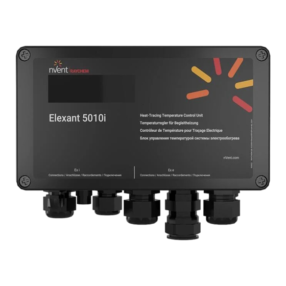
Summary of Contents for nVent RAYCHEM Elexant 5010i
- Page 1 Elexant 5010i Elexant 5010i-LIM Installation Instructions...
- Page 2 *For 20 mm gland/ für 20 mm Verschraubung/ pour presse-étoupe 20 mm/ для 20-мм сальника **For 20/25 adapter/ für 20/25 Adapter/ pour un adaptateur 20/25/ для переходника 20/25 Figure 2: Dimensions/ Abmessungen/ Dimensions Elexant 5010i(-LIM) Elexant 5010i-LIM Heat-Tracing Temperature Control Unit with Safety Limiter Temperaturregler mit Sicherheitstemperaturbegrenzer Contrôleur/Limiteur de température pour traçage électrique...
- Page 3 Figure 3: connection diagram/ Anschlussplan/ Schéma de connexion/ Схема подключения Elexant 5010i RS-485 cable coming RS-485 cable going to from previous device next device RTD Lim RS-485 – RTD 2 RS-485 – RTD 1 Internal End Of Alarm line resistor...
- Page 4 Elexant 5010i & Elexant 5010i LIM II 2 G Ex eb ib mb [ib] IIC T4 Gb UL 22 ATEX 2446X II 2 D Ex tb [ib] IIIC T67°C Db IP66 –50°C ≤Tamb ≤+60°C Ex eb ib mb [ib] IIC T4 Gb IECEx UL 22.0034X...
- Page 5 ENGLISH Warning: The purchaser should make the manufacturer aware of any external effects or aggressive substances that the equipment may be exposed to. The cable glands shall only be used for fixed installations, the cables must be fixed to prevent pulling or twisting. Important Notice: In case a failure of the safety system is detected either during operation or during routine maintenance when executing a function test the unit should be switched off and taken out of service.
- Page 6 The Elexant 5010i-(LIM) consists of a temperature controller and an additional safety temperature limiter. Elexant 5010i-(LIM) units are approved for use in hazardous area Zone 1 and Zone 2 (Gas) and Zone 21 and Zone 22 (Dust).
- Page 7 Measuring ranges Temperature range controller From –200°C to +700°C in steps of 1K Temperature range limiter From +50°C to +599°C in steps of 1K (Elexant 5010i-LIM only) Voltage From 90 Vac to 305 Vac Load current From 0.1 A to 25 A Ground fault current From 10 mA to 500 mA (RCD/ELCB required due to IEC and/or local regulations).
-
Page 8: Mechanical Installation
4 mounting holes. Up to a pipe temperature of 210°C the Elexant 5010i and Elexant 5010i-LIM units can be mounted directly on the pipe by means of a support bracket type SB-125. Ensure that the ambient temperature of the equipment does not exceed 60°C at any time. -
Page 9: Temperature Sensors
The Elexant 5010i/Elexant 5010i-LIM temperature inputs are designed as intrinsically safe circuits (IEC 60079-11/EN60079-11 Ex [ib]) therefore any type of three wire DIN IEC 751 Class B PT100 resistance temperature devices can be used. The Elexant 5010i-LIM supports 3 local temperature inputs, where 2 are allocated to the temperature controller (RTD 1 and RTD 2). The third temperature input is reserved for the temperature limiter (RTD limiter). -
Page 10: Electrical Installation
1.1.5 Communication and networking The Elexant 5010i controller is equipped with a RS-485 interface. Through this interface up to 247 Elexant 5010i units can be networked to a NGC-UIT/TOUCH 1500 or to one serial port of standard PC running Windows based Supervisor software. -
Page 11: Maintenance
In order to manually reset the limiter after it has tripped, the user needs to press the RESET button, under the lid of the Elexant 5010i enclosure (shown in the Figure below). Alternatively, the limiter can be reset remotely using Supervisor software, Android tablet, or other supervisory software. -
Page 12: Functional Test
3.1.4.2 Configuring the limiter set point Modifying the set point requires physical access to the Elexant 5010i device. The lock out set point may be configured with any supervisory software that allows the user to be physically close to the 5010i device. The procedure to modify the limiter set point is the same for all user interfaces. - Page 13 3.1.10 Determining safety integrity of the Elexant 5010i-LIM The Elexant 5010i-LIM is a Type B system, as defined in IEC61508-2:2010. A sub-system is a Type B system when all of the following apply: 1. The failure mode of at least one component that is used is not adequately defined.
- Page 14 3.1.12 System failure modes When using the Elexant 5010i Limiter variant in a safety critical application, it is necessary to consider the failure mode of all elements, and the probabilities of those failures, in order to understand their possible effect, and what mitigation may be necessary. The table below summarizes the failure modes of this element.
- Page 15 nVent.com/RAYCHEM...
- Page 16 Europe, Middle East, Africa Asia Pacific Tel +32.16.213.511 Tel +86.21.2412.1688 Fax +32.16.213.604 Fax +86.21.5426.3167 thermal.info@nVent.com cn.thermal.info@nVent.com nVent.com/RAYCHEM ©2023 nVent. All nVent marks and logos are owned or licensed by nVent Services GmbH or its affiliates. All other trademarks are the property of their respective owners. nVent reserves the right to change specifications without notice.

Need help?
Do you have a question about the Elexant 5010i and is the answer not in the manual?
Questions and answers