
Related Manuals for Warner Electric MCS202-E1

Summary of Contents for Warner Electric MCS202-E1
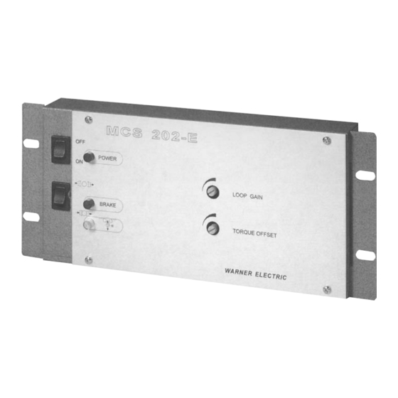
- Page 1 WARNER ELECTRIC MCS202-E1 MCS202-E154 MCS202-EC1 User Manual WARNER ELECTRIC EUROPE Rue Champfleur, B.P. 20095, F- 49182 St Barthélemy d’Anjou Cedex Tél. +33 (0)2 41 21 24 24, Fax + 33 (0)2 41 21 24 00 www.warnerelectric-eu.com MC403WEr-gb-1003 Page 1 of 3...
- Page 2 The electronic circuit utilises a single +15 VDC power source. The supply voltage for the sensor is +15 VDC, the sensor signal should be minimum +3 VDC and maximum 10 VDC. When the Warner Electric sensor MCS605-E is used it should be operated within a +/–30°...
- Page 3 START-UP (based on employing a Warner Electric MCS605-E dancer arm sensor) 1. Mount sensor on dancer arm. Align both marks on the shaft and flange with the desired dancer arm operating position. Make sure that the operating band for free dancer arm motion is at least +/– 30° around this operating position.