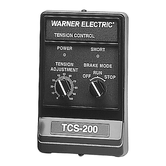
Summary of Contents for Warner Electric TCS-200
- Page 1 TCS-200 Tension Control Installation & Operating Instructions P-2106-WE 819-0550 An Altra Industrial Motion Company...
-
Page 2: Table Of Contents
Figure 2 Power and Brake Connections . . . . . . . . . . 6 When the TCS-200 is operated in a remote torque or roll follower adjust mode, a 1000 ohm potentiometer is Figure 3 Remote Sensor and Switch required . -
Page 3: Theory Of Operation
. The “brake-on” input provides for The TCS-200 rectifies the 24 to 28 VAC to provide a full output current to the brake . usable DC voltage level for powering the internal logic as well as supplying current for brake operation . -
Page 4: Technical Specifications
115/230VAC 24V@6amps Triad F-260-U 115VAC 24V@6amps Potentiometers Remote Torque Adjust 1000ohms, 10% tolerance, .5% linearity, .5watts, linear taper Roll Follower 1000ohms, 10% tolerance, .5% linearity, .5watts, linear taper 4 Warner Electric • 800-825-9050 P-2106-WE • 819-0550... -
Page 5: External Sensor
INSTALLATION This Installation and Operation Manual was arranged for 4 . Attach the TCS-200 control chassis to the the systematic installation and start-up of your tension mounting surface and secure with mounting control system . For this reason, and to achieve the best hardware (not provided, customer supplied) . -
Page 6: System Wiring
5 . Under no circumstances should auxiliary accessories 1 . Mount the roll follower potentiometer and be operated from the TCS-200 control . determine the amount of angular rotation at the 6 . Do not attempt to incorporate external switching potentiometer shaft . - Page 7 AC power to the transformer and secondary magnet to terminal 4 of terminal strip TB1 of the AC power to the TCS-200 are segregated and not run TCS-200 . This becomes the sense magnet . common to other AC circuits in the control panel .
- Page 8 4 operation . Before applying power to the system, double of terminal . strip TB2 of the TCS-200 . Do not check the wiring and installation for proper hook-up and tighten the terminal screw . Snug down only .
-
Page 9: System Start-Up And Adjustment
13 . Remove the meter from in series with the sense magnet and terminal 4 of terminal strip TB1 . 16 . Attach the cover to the control chassis using the two cover screws supplied with the control . Warner Electric • 800-825-9050 P-2106-WE • 819-0550... - Page 10 DC should be used . Connect positive (+) to terminal 25 . Re-attach the cover using two cover screws 2 and negative(-) to terminal 4 . supplied with the control . 10 Warner Electric • 800-825-9050 P-2106-WE • 819-0550...
-
Page 11: Data
Remove shorted magnet coil and replace . Brake connections improperly wired Check wiring and rewire if necessary . Transient noise Check for source of noise and suppress . Segregate wiring . Use shielded cable . Warner Electric • 800-825-9050 P-2106-WE • 819-0550... - Page 12 Recheck wiring and magnet connections and rewire if necessary . Local or remote tension adjust incorrectly set Recheck set-up procedures for the mode of operation the control is used in . Readjust if necessary . 12 Warner Electric • 800-825-9050 P-2106-WE • 819-0550...
- Page 13 NOTES Warner Electric • 800-825-9050 P-2106-WE • 819-0550...
- Page 14 Warner Electric LLC be liable for consequential, indirect, or incidental damages of any kind incurred by reason of the manufacture, sale or use of any defective product . Warner Electric LLC neither assumes nor authorizes any other person to give any other warranty or to assume any other obligation or liability on its behalf .


Need help?
Do you have a question about the TCS-200 and is the answer not in the manual?
Questions and answers