Sign In
Upload
Download
Add to my manuals
Delete from my manuals
Share
URL of this page:
HTML Link:
Bookmark this page
Add
Manual will be automatically added to "My Manuals"
Print this page
×
Bookmark added
×
Added to my manuals
Manuals
Brands
Xeltek Manuals
Motherboard
SuperPro 611S
Manual
Xeltek SUPERPRO 611S Manual
Universal programmers
Hide thumbs
Also See for SUPERPRO 611S
:
Manual
(26 pages)
1
2
3
4
5
6
7
8
9
10
11
12
13
14
15
16
17
18
19
20
21
22
23
24
25
26
27
28
29
30
31
32
33
34
35
36
37
38
39
40
41
42
43
44
45
46
47
48
49
50
51
52
53
54
55
56
57
58
59
60
61
62
63
64
page
of
64
Go
/
64
Bookmarks
Advertisement
Quick Links
Download this manual
®
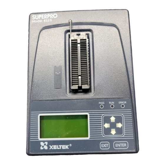
SuperPro
6100 Programmer
®
SUPERPRO
6100, 611S, 610P
Universal Programmers
www.xeltek.com
1 / 64
1296 Kifer Rd. Suite #605
sales@xeltek.com
Sunnyvale, CA 94086
Tel: +1 408-530-8080
Fax: +1 408530-0096
Previous
Page
Next
Page
1
2
3
4
5
Advertisement
Need help?
Do you have a question about the SUPERPRO 611S and is the answer not in the manual?
Ask a question
Questions and answers
Related Manuals for Xeltek SUPERPRO 611S
Motherboard Xeltek SuperPro 6100 Manual
(26 pages)
Motherboard Xeltek SUPERPRO 6100N Manual
Universal programmers (64 pages)
Motherboard Xeltek Superpro SB02 User Manual
(19 pages)
Motherboard Xeltek Superpro 7500 Series User Manual
Ultra-fast, stand-alone, 144pin programmer of the future (49 pages)
Motherboard Xeltek Superpro IS416 Series User Manual
Ultra-fast, in-system, 16 channels programmer of the future (56 pages)
Motherboard Xeltek SUPERPRO Series User Manual
Universal programmers for windows 95/98/nt/2000 (28 pages)
Motherboard Xeltek Superpro SP7500 User Manual
(19 pages)
Motherboard Xeltek SUPERPOR/6100N Manual
(67 pages)
Motherboard Xeltek SUPERPRO 9000U Operation Instructions
Stand-alone mode (2 pages)
Motherboard Xeltek SUPERPRO 2000 Operation Instructions
Stand-alone mode (2 pages)
This manual is also suitable for:
Superpro 6100
Superpro 610p
Superpro 6100n
Print
Rename the bookmark
Delete bookmark?
Delete from my manuals?
Login
Sign In
OR
Sign in with Facebook
Sign in with Google
Upload manual
Upload from disk
Upload from URL


Need help?
Do you have a question about the SUPERPRO 611S and is the answer not in the manual?
Questions and answers