Floor standing oil-fired condensing boiler using room sealed flue for fully pumped open vent or sealed central heating systems and domestic hot water cylinders (48 pages)
Summary of Contents for Bosch WORCESTER Greenstar Heatslave II 12/18
Page 1
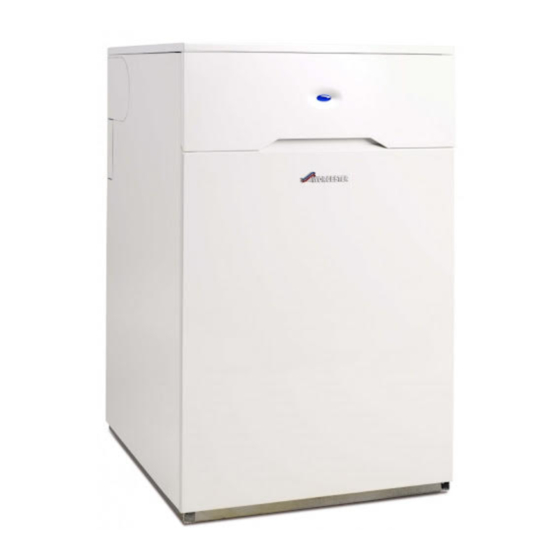
Installation, Commissioning and Servicing instruction manual Floor Standing oil-fired Condensing Combination Boiler using Conventional and Room Sealed Flue 2022+ Greenstar Heatslave II 12/18, 18/25 & 25/32 For fully pumped sealed central heating systems and mains pressure domestic hot water. These appliances are for use with Kerosene (Class C2) only.
Key to symbols and safety instructions List entries, first and second levels Key to symbols and safety instructions • A single component/item • A component/list, made up of multiple parts/items. Key to symbols – Sub component or sub list of main component/list. Warnings –...
Page 4
Key to symbols and safety instructions Oil fumes or leaks from the appliance Flue systems must not be modified in any way other than as described in the fitting instructions. If you smell oil fumes, observe the following rules. Any misuse or unauthorised modifications to the appliance, flue or ▶...
Installation regulations Local water company bye-laws. Installation regulations The Control of Pollution (Oil) Regulations. OFTEC Standards. Complying with the building regulations Where no specific instruction is given, reference should be made to the This heating appliance forms part of the controlled services for the relevant codes of practice.
Appliance information Description Units 12/18 18/25 25/32 Appliance information Pipework connections Fuel line (compression) General information CH flow Standard package CH return Water main inlet DHW outlet CH drain hose connection Condensate (polypropylene) 21.5 21.5 21.5 Electrical Electrical power supply voltage AC.
Appliance information Energy efficiency The following product data satisfy the requirements of the EU Regulations No. 811/2013 and No. 812/2013 supplementing Directive 2010/30/EU. Symbo Product data Unit 7731600260 7731600261 7731600262 2022 + 2022 + 2022 + Product type – – Greenstar Heatslave II Greenstar Heatslave II Greenstar Heatslave II...
Appliance information Layout & components The diagram below excludes the top, front and RH side casing panels. 51 50 31 32 Fig. 2 Greenstar Heatslave II 2022 + 6 721 843 978 (2022/01)
Page 9
Appliance information CAUTION: Isolate the mains supplies before starting any CONTROL BOX ASSEMBLY work and observe all relevant safety precautions. SERVICE MODE BUTTON CH TEMPERATURE CONTROL KNOB LCD DISPLAY CASING SIDE PANEL FLUE "KNOCK-OUT" SECTION TANK TEMPERATURE CONTROL KNOB DIAGNOSIS PORT - WORCESTER ENGINEER SYSTEM PRESSURE GAUGE [10] FLUE GAS SAMPLING POINT [11] FLUE MANIFOLD COVER...
▶ In cases where all attempts to find a system micro reduce efficiency. Failure to comply with the guidelines leak have failed, Worcester, Bosch Group supports for the use of water treatment with the appliance will the use of Fernox F4 leak sealer.
Pre-Installation Mains water pressure • Plastic or steel tanks should be installed to BS 5410. A steel tank should conform to BS 799: part 5 and have a slope of NOTICE: Boiler damage 1:24 away from the outlet with a sludge cock at the lower end. ▶...
Pre-Installation 4.3.2 Double pipe sub-gravity feed system: 4.3.4 Pipework Maximum suction height 3.5 m. Non-return valves must be fitted to the ▶ Refer to the oil supply sections Single pipe gravity feed inlet and return oil line between the oil pump [9] and oil storage tank [1]. system: 4.3.1, Double pipe sub-gravity feed system: 4.3.2 &...
Pre-Installation Water systems and pipework The boiler should not be allowed to operate with a return temperature of less than 30°C when the system is up to operating temperature. Oil burners cannot modulate to accommodate a reduction in heating loads. If the heating load can be significantly reduced due to TRV’s or zoning of the heating circuits, consideration should be given as to how 6720805209-82.1Wo...
Page 14
Pre-Installation Showers/Bidets: • If a shower head can be immersed in water or comes closer than 25mm from the top edge of a bath or shower tray spill over level then an anti-siphon device must be fitted to the shower hose. Only thermostatically controlled showers are suitable for use with this appliance.
Pre-Installation Condensate discharge Soil stack connection Full details on condensate discharge. figure 11 ▶ Follow the latest version of BS6798 and HHIC In order to minimise risk of freezing during prolonged cold spells, the guidance. following methods of installing condensate drainage pipe should be adopted, in order of priority.
Pre-Installation Condensate pump ▶ The external run be kept as short as possible and ideally should not figure 13 exceed three metres. Additional precaution against freezing must be taken if the external Where direct connection to “gravity discharge” is not physically pipe run does exceed three metres.
Page 17
Pre-Installation Good practice ▶ The following guidance indicates the good practices that must be maintained for the Installation and Maintenance of a product. Rain water down pipe with external air break figure 15 • Refer to the following example to dispose of condensate to a rain water down pipe.
Pre-Installation 400mm min. 25mm min. 500mm min. 0010036808-001 Fig. 18 To a soak-away Pressure relief pipework • The pressure relief discharge pipe [1] should be at least 15 mm diameter copper pipe and run downwards away from the boiler and discharge away from any electrical or other hazard, preferably to an external drain or soak away.
Page 19
Pre-Installation To provide sufficient air a suitable inlet must be provided into the room Maintenance clearances or space in which the boiler is situated. Figure 22 shows the clearances required for maintenance. * Remove the flue "knock-out" panel sections if this clearance is less than Output 12/18 18/25...
Pre-Installation Rooms containing a bath or shower Flue gas system considerations WARNING: Conventional flues CAUTION: Non accessible flue systems: ▶ Conventional flue boilers must not be installed in a ▶ Where a flue system is not going to be accessible, bathroom provision must be made for service and inspection.
Page 22
Pre-Installation 13. 300mm adjacent to a boundary line unless it will cause a nuisance. NOTICE: BS 5410: Part 1 recommended that care is taken when siting ▶ All measurements are the minimum clearances terminal in relation to boundary lines. required. 14.
Pre-Installation Flue options A carbon monoxide detector conforming to BS EN 50291-1 should be installed in accordance with the manufacturer’s instructions. 4.9.1 Conventional flue (CF) • Open (conventional) flued appliances must not be installed in a bedroom, bathroom, bed-sitting room, or garage. •...
Pre-Installation 4.9.2 Room sealed flue options Figure 26 shows the components used and the maximum flue length [L] for each flue configuration. In all cases L is measured from the outside of the boiler casing. • To achieve the maximum flue length [L], a flue section will have to be L = 120 - 240mm L = 6000mm reduced in length.
Pre-Installation 4.10 PLUME MANAGEMENT FLUE TERMINAL GUARD ±45° 7 716 191 176 2500 2500 ≥140 ≥ 5 ≥ 5 0 0 5 0 0 ±80° EXCLUSION ZONE A EXCLUSION ZONE A EXCLUSION ZONE A 1000 2500 1000 2500 2500 1000 1800 1200 BOUNDARY LINE...
Page 26
Pre-Installation 12. The distance between a boundary facing a terminal can be measured diagonally from the point of discharge with a minimum distance of 600mm which must be maintained. The exclusion zone ensures compliance with Approved Document J of the building regulations, 13.
Installation Pipework positions and flue opening Installation CAUTION: Ensure there are no pipes, electric cables, Unpacking the boiler damp proof courses or other hazards before drilling. Lifting and carrying precautions: ▶ Lift only a manageable weight, or ask for help. Safety ▶...
Installation 6 720 805 209-06.1TL Fig. 30 770** Fig. 31 [**] IMPORTANT: for horizontal flues, increase this height by 5.2mm for every 100mm of horizontal length that the flue opening is away from the boiler. Fig. 32 Boiler installation ▶ Lift the top panel [A] upwards to disengage the ball stud connections [B] and remove.
Installation Flue installation Insert the flue damper into the inner tube of the straight extension or 90° elbow and fit the flue as shown in figure 34. Ensure that the rubber seal The flue can exit the boiler from outlets A, B, C or D for vertical (RS) and is fitted into the inner tube.
Installation Combustion chamber Pipework connections ▶ Unscrew screws [G] and remove flue manifold access cover [H]. CAUTION: Isolate the oil & water mains supply before ▶ Check that all the baffles [J] and baffle retainer [K] are correctly starting any work and observe all relevant safety fitted to the secondary heat exchanger.
Installation Pressure relief connection Fire valve ▶ Connect the pressure relief pipe [N] to a copper discharge pipe Check that the oil supply pipe has a fire valve fitted externally to the (15mm Ø min.). building with the fire valve sensor located in the case. A fire valve sensor clip [1] is provided for this purpose on the support bar between the side panels.
Installation Fig. 42 Converting to double pipe system Return plug By-pass screw Return pipe connection Refitting components 6720821683-12.1Wo Fig. 40 Nozzle access WARNING: Flue gas leakage. The seal between the burner and the mounting flange Refer to figure 41: must form a gas tight seal to prevent leakage of ▶...
Page 33
Installation 3. Plug burner lead [F] into connector [G]. 4. Swivel the expansion vessel [H] back into position taking care not to kink the flexible hose or snag electric cables. 5. Refit control box. ▶ Rotate the box towards you [J]. ▶...
Installation Electrical DANGER: ISOLATE THE 230V ELECTRICITY SUPPLY ▶ Ensure that the electricity supply is safely Isolated and secured to prevent inadvertent re-connection. Information on safe isolation can be found in the Health and Safety Executive guidance HSG85. Using test equipment approved to GS38 confirm that the electricity supply is disconnected.
Page 35
Installation Fitting the programmer/timer 1. If your programmer has a ribbon cable, connect the ribbon cable to the socket [D] in the control panel, ensuring the cable will fit into the recess [E] in the control panel. If your programmer does not have a ribbon cable then the EMS connections will be utilised to make connection to the boiler.
Installation 5.11 Weather compensation The sensor is wired directly into the control box via terminal 4 in the low voltage terminal strip ( page 34). The appliance will modulate the CH flow temperature based on the outside temperature when an outdoor sensor is connected to the The heating curve outdoor sensor connection on the control board and the weather The CH flow temperature has an upper limit of 82°C (this can be capped...
Commissioning Filling the system Commissioning 1. The diverter valve will sit in mid-position when the boiler has no demand and is powered up. Pre-commissioning checks-appliance CAUTION: Isolate the mains supplies before starting any work and observe relevant safety precautions. 1. Check that the service and water pipes are connected correctly. 2.
Commissioning ▶ Turn on the water main stop cock. – The use of an oil suction pump will prime and flush through any oil supply set up simply and easily, alternatively the following ▶ Close the flow pipe manual air vent when water is vented. procedures can be used.
Commissioning 6.3.3 Burner head setting Adjustments to the burner head are made on the basis of the required output, refer to table 9 for the required setting for your boiler. Fig. 61 Priming the pump Fig. 63 Burner head adjustment thumbwheel Oil supply De-aerator One complete rotation clockwise (cw) from the minimum position...
Commissioning 6.3.4 Boiler lockout Smoke readings may be inaccurate until the smoke from If the burner fails to establish a normal firing pattern or flame failure burning organic binder in the access door insulation has occurs the flame monitoring photocell mounted in the burner body will ceased.
Page 42
Commissioning 6 720 805 209-39.1TL Fig. 70 Central heating symbol Displays this symbol during CH demand. Hot water symbol Displays this symbol during DHW demand (DHW flow rate > 2 litres per minute) and tank reheat. Weather Compensation active symbol Displays this symbol only if a Weather Compensation sensor has been fitted to the appliance and is active.
Commissioning 6.3.6 Selecting Service Menus To modify setting 1. Press and hold buttons together for 1 second, the 1. Select the desired menu option using the arrow buttons (refer to display will show Menu 1. figure 74) and press the OK button, the option will flash. Double up or down arrows indicate that the menu can only be ▶...
Commissioning ▶ Refit the blanking plug [1]. ▶ Check and rectify any oil leaks. 1. Switch on the oil supply. ▶ Switch on the electrical supply. ▶ Restart the boiler and run for 5 minutes. ▶ Recheck the CO2 levels and if required, adjust the air shutter setting [4] to obtain the correct CO level.
▶ Use a radiator key or suitable screwdriver to open the vent point. content is lost. ▶ In cases where all attempts to find a micro leak have failed, Worcester, Bosch Group supports the use of Fernox F4 leak sealer. Water treatment products...
• During the period of this guarantee any appliance components that are proven to be faulty or defective in manufacture will be exchanged or repaired free of charge by Bosch Thermotechnology Ltd. • The householder may be asked to prove the date of installation, that...
Page 47
Service and Spares 4. Unscrew burner retaining nut [12] and remove the burner [13] and ▶ Reassemble the components. store safely away from the boiler. 6720821683-13.1Wo Fig. 82 Fan access Oil burner nozzle Before removing or fitting a new nozzle refer to figure 83: ▶...
Page 48
Service and Spares ▶ To align the hole [9] in the break plate with the photocell, ensure that ▶ Check the O-ring seal located around the combustion head and the fixing screw [3] is located fully in the seating [7] provided in the replace if necessary.
Page 49
Service and Spares ▶ Remove the one piece baffle set [C], clean and check the condition 12/18 Baffle of the baffles. Replace baffle set if considered to be badly corroded/ degraded. ▶ Thoroughly clean all of the heat exchanger surfaces using a suitable brush and clear all loose debris from the combustion chamber.
Page 50
Spares that the smoke reading is between 0 and 1, if the smoke reading is For Worcester Bosch spares refer to the the website at www.worcester- above one check the air setting. If the air setting is correct check that bosch.co.uk/spares...
Fault finding and diagnosis Fault finding and diagnosis Status cause codes These cause codes are displayed during the normal operation of the boiler. They are not faults, they just give information on the current status of the boiler in real time. During normal operation various status codes can be displayed by pressing the service button.
Fault finding and diagnosis i13 Thermal This is the thermal store current temperature, store displayed in real time (rounded to 0.5°C units). current temperatur i14 DCW inlet Current DCW inlet temperature, displayed in real temperatur time (rounded to 0.5°C units). i15 Out door This is the out door temperature displayed in real temperatur...
Fault finding and diagnosis 6 720 805 209-67.1TL Fig. 97 2.7A Demand/fault O = The blue light will only LED (blue light) activation operate as a flashing fault alert. 6 720 805 209-68.1TL Fig. 99 1 = The blue light will operate 8.4.2 Locking or Blocking fault conditions as a boiler operation and...
Fault finding and diagnosis 8.4.3 Cause and fault codes Cause Fault Reset code code Description type Blocking Locking Possible cause/solution Maximum temperature thermostat or Reset Flue gas or tank thermostat overheat. Reset the overheat air pressure switch activated thermostat or air pressure switch before resetting appliance. No code Safety or flow temperature too high Air lock or reduced water content.
Fault finding and diagnosis CH function chart Flow temp peaks: Flow at more than Burner CH setpoint minus CH adaptive offset CH adaptive setpoint adjusted [200] [200] [200] 230V on CH LR AND fascia mounted Flow temp less than NO DEMAND Blue light ON Appliance Pump...
Fault finding and diagnosis Protection functions Frost Protection Appliance: PHE OR Flow PHE OR Flow Pump OFF Pump 3WV to Waiting period sensor below 3WV to CH sensor below after 5 of 25 ninutes 8°C 9°C minutes Appliance automatic frost protection ( monitors PHE, flow and internal PHE AND...
Fault finding and diagnosis Solar compatibility DCW in less than Normal DHW 40°C operation Burner OFF for DCW in more than DHW 10 l/min & 40°C (but less above (burn than 3 below) allowed for tank (for 2 sec or more) reheat during demand) During a DHW demand...
Fault finding and diagnosis 8.10 Riello digital control boxes Anomaly types (Burner in stand-by) 8.10.1 Control box LED codes Green 0.5 s ON / Lockout types (burner in lockout) Green 2.5 s OFF Fit pre-heat link Refer to Fault finding chart, section 8.10.2, go to line number on chart Pre-heating time RED steady ON Lockout for no flame after safety time...
Page 60
Fault finding and diagnosis Line Check Action Motor runs for less than 12 seconds? Go to line 4a Go to line 5 Motor gives 50 Volts a.c. across black and white wires? Replace control box Replace fan motor Burner does not fire, burner locks out after 25 seconds from motor start? Go to line 5a Go to line 6 Burner fires when the photo cell is covered?
Fault finding and diagnosis 8.11 Flame sensing photocell ▶ Press the air pressure reset button [4], located on the underside of the support bracket [2]. Digital photocell -or- To check the correct functioning of the photocell, perform the following If the tank exceeds a set temperature value the thermostat will trip. actions: ▶...
Fault finding and diagnosis 8.14 Air pressure switch connections NOTICE: APS pressure sensing tubes ▶ Ensure that the pressure sensing tubes are not kinked or trapped when working on the boiler. ▶ Kinked or trapped tubes will prevent the APS from functioning correctly Air pressure switch sensing tube connections: ▶...
Page 63
Fault finding and diagnosis Is the system pressure constantly increasing even when the boiler is off for extended periods of time? PRV = Pressure Relief Valve EV = Expansion Vessel Does system pressure Can you confirm that the filling increase when the link is not stuck open/passing boiler is on? water in any way?
Fault finding and diagnosis 8.16 Oil appliance commissioning checklist IMPORTANT This Commissioning checklist is to be completed in full by the competent ▶ Leave this manual with the Homeowner. person who commissioned the appliance as a means of demonstrating compliance with the appropriate Building Regulations and then handed to the customer to keep for future reference.
Fault finding and diagnosis 8.17 Service interval record Before completing the service Interval record below, ensure that you have carried out the service functions described in this manual. It is recommended that your appliance is serviced annually and that the Service Interval Record is completed and signed.