
Related Manuals for Lincoln SKF eLube DataLog 85139


Summary of Contents for Lincoln SKF eLube DataLog 85139
- Page 1 User and maintenance instructions SKF eLube DataLog controller Model Date of issue December Form number Version ...
-
Page 2: Table Of Contents
Contents Safety ............. -
Page 3: Safety
Explanation of signal Safety CAUTION words for safety Do not operate equipment without Read and carefully observe operating wearing personal protective gear. instructions before unpacking and operating Wear eye protection. Protective equipment. Equipment must be operated, equipment such as dust mask, non-skid maintained and repaired exclusively by safety shoes, hard hat, or hearing pro- NOTE... -
Page 4: Description
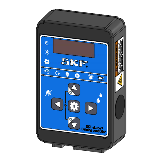
Description Table Specifications Controller is a universal electronic unit Voltage V to V nominal designed to control automated lubrication Current drain mA (no load) systems and collect log files. Current drain (standby mode) mA maximum Single line parallel and progressive sys- Output capacities tems can be controlled by this controller. -
Page 5: Key Ignition Mode
Key ignition mode Heavy working mode NOTE Do not exceed system voltage at IGN- pin. Controller features a key ignition mode. Controller features a Heavy Working Mode If controller is expected to remain in With “Ignition Input Present?” set to “Yes”, that can be quickly enabled or disabled when standby mode for over ... -
Page 6: Led Code Descriptions
Table LED code descriptions Panel display Description Run time. In timed mode, this defines the pump run time per lubrication cycle. In switch mode, this defines pump max run time until an error is signaled. Pause time. Defines pause time between lubrication cycles. Heavy mode pause time. -
Page 7: Front Panel Configuration
Front panel The up/down navigation keys will change the • Heavy pause time = minutes current selection and adjust values when • Pre-lube mode = always configuration applicable. • Control mode = switch Unauthorized access to settings mode can •... -
Page 8: Single Line
Fig. Single line Time setting input Pin input Pin configured Hour Digit Digit Digit Digit D/H/M/S:XY Incorrect (Err) Correct System type selection Max run time Time setting input (MM:SS) Single line Pin not configured Default 02:00 Save and Progressive line return Pause time Time setting input (DD:HH:MM:SS) -
Page 9: Progressive Line
Table Progressive line Menu level Menu level Menu level Menu level Notes Progressive (Pro) Max run time (run) Set time (MM:SS) Time limits: Pause time (Pt) Set time (DD:HH:MM:SS) Days: - Heavy mode pause time (HPt) Set time (DD:HH:MM:SS) Hours: -... -
Page 10: Progressive Line
Fig. Progressive line Time setting input Pin input Pin configured Hour Digit Digit Digit Digit D/H/M/S:XY Incorrect (Err) Correct System type selection Pin not configured Single line See single line config Progressive line Max run time Time setting input (MM:SS) Default 02:00 Save and return... -
Page 11: Wiring Examples
Wiring examples Fig. Fig. Single line system with pressure switch, external indicator, & Single line w/ pressure switch, external indicator, and low level input Single line with pressure switch, external indicator, and low level low level sensor. Diagram depicts use of optional high current sensor. -
Page 12: Replace Fuse
Replace fuse WARNING Do not open controller with power supply to controller on Turn power off prior to opening Failure to comply will result in death or serious injury 1 Remove screws (1) located on back of controller 2 Remove and replace mini blade fuse (2) 3 Install back plate 4 Install screws (1) into back of controller Fig. -
Page 13: Connecting Skf Elube Datalog Controller To Skf Elube App
Connecting SKF eLube Datalog controller to SKF eLube app 1 Download app from respective app store (available for Android and Apple environments) 2 Power on SKF eLube DataLog controller 3 Open SKF eLube app, the text <Lube sys- tems nearby= will be visible towards the top of the page 4 Select desired eLube DataLog controller to connect... -
Page 14: Adjusting System Parameters Within Skf Elube App
Adjusting system parameters within SKF eLube app 1 Select settings tab. 2 Select Edit to open the change settings menu. 3 Adjust settings as desired. NOTE Configurations that were previously saved into the repository can be loaded. 4 Select apply to update parameters to the connected SKF eLube DataLog controller. -
Page 15: Datalog Within Skf Elube App
Datalog within SKF eLube app The controller features the ability to datalog events and errors. This datalog can be viewed and exported from the SKF eLube app. Events consist of notifications about the controller’s state and errors include lubrica- tion faults. Fig. -
Page 16: Warranty
® SKF, Lincoln and SKF eLube are registered trademarks of the SKF Group. © SKF Group The contents of this publication are the copyright of the publisher and may not be reproduced (even extracts) unless prior written permission is granted. Every care has been taken to ensure the accuracy of the information contained in this publication but no liability can be accepted for any loss or damage whether direct, indirect or consequential arising out of the use of the information contained herein.
Need help?
Do you have a question about the SKF eLube DataLog 85139 and is the answer not in the manual?
Questions and answers