
Related Manuals for Reefe RPC-15006


Summary of Contents for Reefe RPC-15006
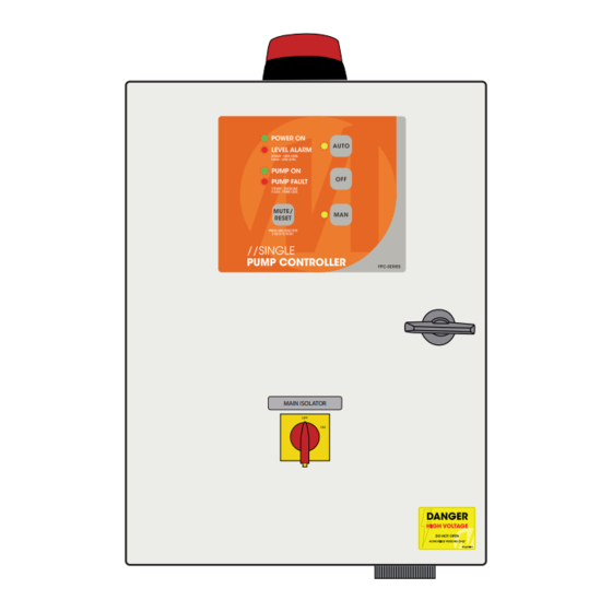
- Page 1 OWNE R’ S OP ERATI ON MANUAL S ingle P um p Co ntro ll e r Ins tal lation a nd O pe ratin g Ins tr uc ti ons MO DEL: RP C-15006 MAIN ISOLATOR DOC: RPC-15006 VER 2.0...
- Page 2 W ELCO ME TO SINGLE PU MP C ONTROL Your Single Pump Controller reflects the superior quality and attention to detail in design, engineering and manufacturing that has distinguished MATelec Products for decades. The controller incorporates the very latest in micro-processor technology, ensuring you, the owner/operator, of many years of functional, reliable and ‘user friendly’...
-
Page 3: Installation
INSTALLATION WIRING CONNECTION DETAIL FPC-15006 2 FLOAT SWITCH SYSTEM MOUNTING INPUT 2 INPUT 3 INPUT 4 FRONT SIDE VIEW 1. Controller enclosure must be STOP START HIGH LEVEL LEVEL LEVEL mounted in a vertical position. SUPPLY PUMP THERMAL INPUT SWITCHES 2. -
Page 4: Operation
OPERA TIO N This controller can perform control functions for most Single Pump pumping applications. It is more than likely that the control parameters have already been set up for your particular application, however, hereunder you will find details of the setup and configuration options. There are 6 DIP switches located on the lower side of the control module, which allows for selecting “mode”... - Page 5 The basic logic on which a High or Low Level Alarm is determined, is set out in the Table below: Input 1 Input 2 Input 3 Input 4 Pump Alarm State Low Level Pump Stop Pump Start High Level Closed Open/Closed Open Open...
- Page 6 In pressure pump mode some of the optional features are disabled, including maximum run alternation, anti-seize and maximum idle timers In order to activate current loop mode the enclosure must be opened and jumper J10 moved to the “current loop enabled”...
-
Page 7: Circuit Diagram
C IRCUIT D IAGRAM CONTACTOR COIL 12Vdc A1 A2 12Vac 240Vac 2amp CIRCUIT BREAKER TRANSFORMER MAIN ISOLATOR INPUT 2 INPUT 3 INPUT 4 DATA STROBE BUZZER SWITCH SWITCH SWITCH OUTPUT 12Vdc 12Vdc 415Vac PUMP... - Page 8 A T A GL ANCE A quick reference to the controller’s Keypad and Indicator functions and meanings. KEYPAD INDI CATO RS PUS H B UTT ONS POWER ON Silences the siren and if held POWER ON Power is turned on. down for 3 seconds, clears all MUTE/ faults...
Need help?
Do you have a question about the RPC-15006 and is the answer not in the manual?
Questions and answers