Table of Contents
Advertisement
Quick Links
Advertisement
Table of Contents

Subscribe to Our Youtube Channel
Related Manuals for Techroutes FE1/100BASE-TX


Summary of Contents for Techroutes FE1/100BASE-TX
- Page 1 FE1/100BASE-TX Bridge USER MANUAL Version: 1.1...
-
Page 2: Table Of Contents
2. Main features ................3 3. Technical specifications ..............5 4. Installation and panel description ..........7 4.1 Unpacking (stand alone FE1/100BASE-TX Bridge) ....7 4.2 Front and rear panel of the stand alone device ....... 7 4.2.1 System test and configuration ......... 10 4.3 Front and rear panel of the rack mount........ -
Page 3: Product Description
In the framing mode, the E1 interface provides a rate of N*64Kbps(N=1~31). In the un-framing mode, the E1 channel provides a rate of 2.048Mbps and accomplishes transparent transmission. If the FE1/100BASE-TX bridge is used in the framing Page 2 of 21... -
Page 4: Main Features
FE1/100BASE-TX Bridge Installation and Operation Manual mode, the transmission clock can be either provided internally, i.e. using the main clocking timing mode (INT), or extracted from the E1 channel, i.e. using slave clock timing mode. The FE1/100BASE-TX bridge provides plenty of self-test functions, supporting local loop and remote loop. - Page 5 FE1/100BASE-TX Bridge Installation and Operation Manual In the E1 framing mode, the number of time slots is optional from 1 to 31. Supporting 2.048Mbps transparent transmission in the E1 un-framing mode. The 100BASE-TX Ethernet interface supports 100M half/ full duplex modes.
-
Page 6: Technical Specifications
FE1/100BASE-TX Bridge Installation and Operation Manual the Bridge of rack mount architecture, assuring high reliability. Support local Hypber Terminal management via RS232 serial port and remoter management by Telnet、 Web、SNMP and CGI management software. Can be communicate with the bridge of other company. - Page 7 FE1/100BASE-TX Bridge Installation and Operation Manual Transmission range: circuit interface: BNC: 600m; RJ45: 300m; Data interface: 100m Indicator: indicating power, connection states of data and circuit interfaces, operation state, test state and trouble alarm. Dimensions: stand alone: 140mm (dep) x 210mm (wid) x 40mm (hei) Rack mount: 19in standard 4.5U cabinet...
-
Page 8: Installation And Panel Description
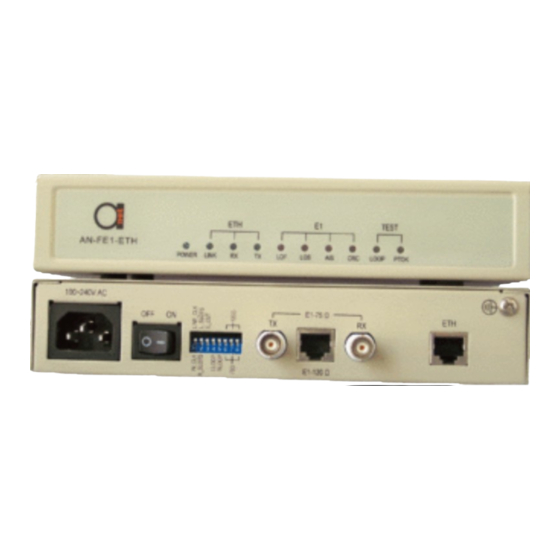
■ Box up list In case of any damage in transportation, contact our offices or agencies. 4.2 Front and rear panel of the stand alone device The front panel of the FE1/100BASE-TX Bridge is shown in figure 2. FE1/ETH TEST TEST... - Page 9 FE1/100BASE-TX Bridge Installation and Operation Manual LINK: Link. Always lights if the data link is complete. RX: Data reception. Flickers when the data interface receives data. TX: Data transmission. Flickers when the data interface transmits data. LOF: Alarm indicator lamp for input signal out-of-frame in E1 line.
- Page 10 Note: Circuit pseudo-random sequence test is valid only when the local equipment is in the framing mode and main clock is configured. The AC input rear panel of FE1/100BASE-TX Bridge is shown in figure 3. E1-75? E1-75? E1-120 ?
-
Page 11: System Test And Configuration
FE1/100BASE-TX Bridge Installation and Operation Manual The DC input rear panel of FE1/100BASE-TX Bridge is shown in figure 4. 48V DC E1-75? E1-75? 1 2 3 4 5 6 7 8 1 2 3 4 5 6 7 8... -
Page 12: Front And Rear Panel Of The Rack Mount
FE1/100BASE-TX Bridge Installation and Operation Manual S5.2: Track remote time slot setting or not, on for R-SLOTS, OFF for L-SLOTS (valid only when S5.1 = OFF) S5.3: mode select. ON for allow transmit the data from the Eth interface to the E1 interface and take back when loop test. - Page 13 Figure 6 Rear panel of rack The panel above consists of three different small panels: The small panel of FE1/100BASE-TX bridge module, as shown in figure 7. Figure 7 Panel of FE1/100BASE-TX bridge module See figure 3 about the description of AC input rear panel of...
- Page 14 FE1/100BASE-TX Bridge Installation and Operation Manual component of the small panel. The panel of RACK/AC AC redundant power supply is shown in figure 8. Figure 8 Panel of rack/AC AC redundant power supply 160-270VAC: AC 220V input socket ON OFF: Power converter...
-
Page 15: Applications Of Fe1/100Base-Tx Bridge
FE1/100BASE-TX Bridge Installation and Operation Manual +5V: 5V main power indicator +12V: 12V fan power indicator 5. Applications of FE1/100BASE-TX Bridge 5.1 Definition of balanced twisted-pair wire sequence for RJ45 interface 5.1.1 100BASE-TX interface wire sequence The RJ45 Unshielded twisted-pair for 100BASE-TX interface can use DCE or DTE standard stipulations, it support AUTO MDI/MDX function. -
Page 16: Setting Of E1 Interface Impedance
FE1/100BASE-TX Bridge Installation and Operation Manual from the guide channel just by unscrewing the screws on the module panel. 5.2.1 Setting of E1 interface impedance Bottom coded switch, as shown in Figure 11 : E1 TS E1 TS 1 2 3 4 5 6 7... -
Page 17: Configuration Of Ethernet Connecting Devices
FE1/100BASE-TX Bridge Installation and Operation Manual selected. The rate of E1 interface is completely dependent on the number of the selected time slots. For example: the setting of 3rd switch to “ON” and all other switches to “OFF” indicates that 2nd time slot is selected, at this moment the rate is 64K;... -
Page 18: Simple Self-Test Methods For Devices & E1 Circuits
If the exchange end and the user end is very far away, the E1 circuits of the two FE1/100BASE-TX bridge must be correctly connected first. Otherwise, indicator LOS will always light. Set the device at the exchange end to framing and main clock mode, set S5.5 (RLOOP) to ON, pseudo... -
Page 19: Typical Applications
Mode 2: Extend an Ethernet network with existing twisted pair or coaxial cable. Connected with twisted pair or 75ohm coaxial cable, the E1 ports of FE1/100BASE-TX Bridge support a transmission range of 300m or 600m. Two Ethernet networks at different locations can be bridged by two FE1/100BASE-TX bridge with existing twisted pair or coaxial cable. -
Page 20: Common Questions And Their Maintenance
FE1/100BASE-TX Bridge Installation and Operation Manual 5.6 Common questions and their maintenance (For independent interface converter, reference for frame bridge) Symptoms Causes Remedies power power The power connected. Check the contact indicator does circuit has of the power lines and the not light after a failure. - Page 21 FE1/100BASE-TX Bridge Installation and Operation Manual 1. Check the coaxial cable or Indicator LOS The circuit the UTP5 twisted pair for open always lights signals are circuit and short circuit. Check when lost. whether plugs cable at the positioned. port 2.
Need help?
Do you have a question about the FE1/100BASE-TX and is the answer not in the manual?
Questions and answers