Table of Contents
Advertisement
Quick Links
Advertisement
Table of Contents

Subscribe to Our Youtube Channel
Related Manuals for Techroutes TSR 2900-10


Summary of Contents for Techroutes TSR 2900-10
- Page 1 TSR 2900-10 Hardware Installation Manual...
-
Page 2: Table Of Contents
contents Table of contents Chapter 1 Introduction to TSR2900-10 ......................1 1.1 Appearance Description for Standard Configuration ................. 1 1.2 Systematic Characteristic Parameters ....................3 1.3 ROHS Description ..........................4 Chapter 2 Installation Preparation ........................4 2.1 Caution of Usage ..........................4 2.2 Safety Advice ............................. -
Page 3: Chapter 1 Introduction To Tsr2900-10
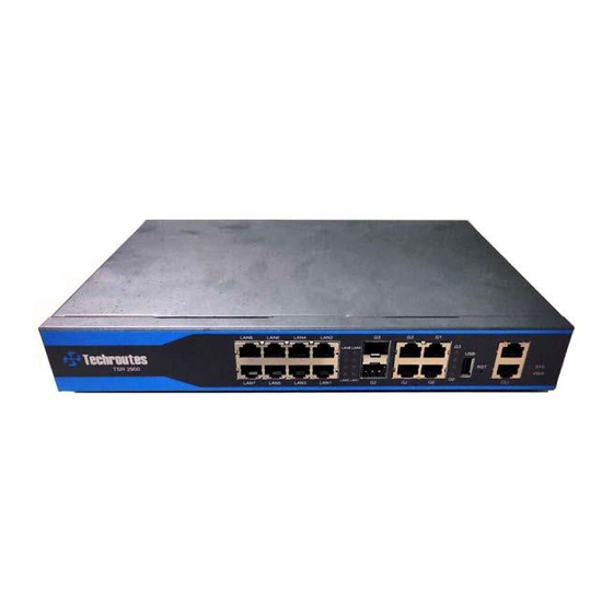
TSR2900-10 Hardware Installation Manual Chapter 1 Introduction to TSR2900-10 This section describes the characteristics and parameters of TSR2900-10 and gives an overview of TSR2900-10. 1.1 Appearance Description for Standard Configuration The built-in ports of TSR2900-10 are: 8 10/100/1000M Ethernet RJ45 LAN ports, 2 10/100/1000M Ethernet RJ45 WAN ports, 2 Combo ports (WAN), 1 Console port, 1 USB port. - Page 4 TSR2900-10 Hardware Installation Manual transmitted. 1000M/100M SFP(WAN), for communication over G2~G3 Gigabit Ethernet SFP 100M/1000M Ethernet SFP; G2, G3 Combo Base-T ports 1000M Ethernet Base-T port (WAN), for communication over 10M/100M/1000M Ethernet Gigabit Ethernet Base-T G0-G3 Base-T port; port G2, G3 Combo ports and G2, G3 Combo Base-T ports If the indicator is on, LINK works;...
-
Page 5: Systematic Characteristic Parameters
TSR2900-10 Hardware Installation Manual Input voltage: 170~264V, AC power input port frequency: 47~63Hz Current: 1A/230V 1.2 Systematic Characteristic Parameters Cavium CN7020 Memory Nor Flash Nand Flash 8Gbit Standard 2 1000M Ethernet optical and Base-T comb ports(WAN) configuration 2 1000M Ethernet Base-T ports (WAN) 8 1000M Ethernet (LAN) 1 Console port 1 USB interface... -
Page 6: Rohs Description
TSR2900-10 Hardware Installation Manual DC power frequency: 47~63Hz Input voltage: 170~264V, Current: 1A/230V 1.3 ROHS Description Chapter 2 Installation Preparation 2.1 Caution of Usage Similar to other electronic products, the semiconductor chip easily gets damaged if you power on or off abruptly and frequently. To restart up the router of TSR2900-10, you have to open the power on-off after the power is cut down for three to five seconds. -
Page 7: Safety Advice
TSR2900-10 Hardware Installation Manual 1) When the lifetime of our products ends, handle them according to national laws and regulations, or send these products to our company for collective processing. 2.2 Safety Advice Safety Principles Keep dustless and clean during or after the installation. ... -
Page 8: Requirements For Common Locations
TSR2900-10 Hardware Installation Manual 4) Do not work alone if potential dangers exist. 5) Cut off the power before checkout. 6) If trouble happens, take the following measures: A. Cut off the system's power. Alarm. Take proper measures to help persons who are hit by the disaster. Artificial respiration is needed if necessary. -
Page 9: Power Requirements
TSR2900-10 Hardware Installation Manual Each device on the cabinet gives off heat when it runs. Therefore, the sealed cabinet must have the heat-discharge outlet and the cooling fan. Do not put the devices too close, avoiding bad ventilation. When you install the machine box at the open cabinet, prevent the frame of the cabinet from blocking the airway of the machine box. -
Page 10: Installation Flow Of Tsr2900-10
TSR2900-10 Hardware Installation Manual 3.1 Installation Flow of TSR2900-10 r o u t e r r o u t e r t o a l o c a t i o n 3.2 Installing the Machine Box of the Router The installation of the machine box has two modes: ... -
Page 11: Connecting The Port
TSR2900-10 Hardware Installation Manual 3.3 Connecting the Port 3.3.1 Connecting the Console Port The TSR2900-10 router has a console port and a remote aux console port. Console port The rate of the console port is a value of 9600bps. It has a standard RJ45 plug with odd-even check. - Page 12 TSR2900-10 Hardware Installation Manual Definition of the pins of the Console port Name Abbrev. Remark None None Send data Output None Signal ground Receive data Input None None The cable is used to connect TSR2900-10 Console port with other terminal devices. - 10...
-
Page 13: Connecting Gigabit Ethernet Ports
TSR2900-10 Hardware Installation Manual 3.3.2 Connecting Gigabit Ethernet Ports TSR2900-10 provides 8 10/100/1000Mbps Base-T ports, 2 1000M combo ports and UTP(RJ45) ports with ACT, Link indicators. In use, the ports can connect other Ethernet The numbering order of the pins in the UTP terminal devices through the UTP port. -
Page 14: Connecting Gigabit Ethernet Sfp Ports
TSR2900-10 Hardware Installation Manual Receiving TP0- sending paraphrase the data 0 Receiving TP1+ sending the normal phase of the data 1 Receiving TP1- sending the of paraphrase data 1 Receiving TP2+ sending the normal phase of the data 2 Receiving TP2- sending paraphrase... -
Page 15: Connecting The Usb Port
TSR2900-10 Hardware Installation Manual 3.3.4 Connecting the USB port The USB port support USB2.0 physical layer protocol USB works in main mode and is connected to the devices with USB interface. Chapter 4 Maintaining Router Caution: Before opening the machine box, make sure that you have released the static you carried and then turn off the power on-off of the router. -
Page 16: Closing The Machine Box
TSR2900-10 Hardware Installation Manual Perform the following steps to open the cover of the router: Turn off the power on-off of the router. Plug out all cables connected the back of the router. Take out the bolt from the machine box with the screwdriver. Note:... -
Page 17: Chapter 5 Hardware Fault Analysis
TSR2900-10 Hardware Installation Manual Chapter 5 Hardware Fault Analysis The part describes how to remove the fault from the router. 5.1 Fault Separation The key for resolving the systematic faults is to separate the fault from the system. You can compare what the system is doing with what the system should do to detect the fault. - Page 18 TSR2900-10 Hardware Installation Manual flickers, the system works well. If the indicator is always on , the LINK works; (LAN)indicator LAN1LAN8 If the indicator flickers, data is transmitted , the LINK If the indicator is always on works; (WAN)indicator G0-G3 If the indicator flickers, data is transmitted Copyright Claims...
Need help?
Do you have a question about the TSR 2900-10 and is the answer not in the manual?
Questions and answers