Advertisement
Quick Links
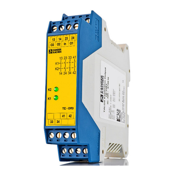
Safety Output-Extension Module TE- OR3
User Information
TE-OR3(D) is an all-purpose safe output-extension module with
Correct Use
three safe relay-contacts. In combination with basic module
TALOS
the moving parts of a machine in case of danger.
TE-OR3(D) extends the safe semiconductor outputs of the basic
module for galvanic isolation and power adjustment.
TE-OR3D is specially designed and certified for the use in
furnaces and ancillary equipment in continuously mode
according to EN 50156-1 and EN 746-2.
Features
3 safe, redundant contacts
•
1 auxiliary contact
Extension of the safe semiconductor outputs of the basic
•
module for galvanic isolation and power adjustment
Cyclical self-monitoring
•
Feedback loop can be used for monitoring by previous
•
basic module (optional)
Configurable on each of the safe outputs of the basic
•
module by setting a jumper at the front of the module
The safe extension module TE-OR3 is designed for safe
Function
isolation of safety circuits according to EN 60204-1 and can
be used up to safety category 4, PL e according to EN ISO
13849-1.
The internal logical system closes the safety contacts when
the safety output of the basic module is switched on.
If the safety output of the basic module is switched off, the
positively driven safety contacts are opened and safely
switch the machine off. It is ensured that a single fault does
not lead to a loss of the safety function and that every fault
is detected by cyclical self-monitoring no later than when
the system is switched off an switched on again.
The use without the basic module is not possible.
As per EN60204-1, the device is intended for installation in
Installation
control cabinets with a minimum degree of protection of
IP54. There has to be an adequate heat dissipation in the
control cabinet. It is mounted on a 35 mm DIN rail
according to EN 60715 TH35 with a pre-installed TBUS-
terminal. The device has to be mounted on the right side of
the basic module. The device will be connected by the
PCB-connector on its backside with the TBUS-terminal.
Safety
Installation and commissioning of the device must be
•
Precaution
performed only by authorized personnel.
Observe the country-specific regulations when installing
•
the device.
The electrical connection of the device is only allowed to
•
be made with the device isolated.
The wiring of the device must comply with the
•
instructions in this user information, otherwise there is a
risk that the safety function will be lost.
It is not allowed to open the device, tamper with the
•
device or bypass the safety devices.
External fusing of the safety contacts must be provided.
Electrical
•
Connection
The line cross section does not have to exceed 2.5 mm
•
If the device does not function after commissioning, it
•
must be returned to the manufacturer unopened.
Opening the device will void the warranty.
H. ZANDER GmbH & Co. KG • Am Gut Wolf 15 • 52070 Aachen • Germany
Tel +49 (0)241 9105010 • Fax +49 (0)241 91050138 • info@zander-aachen.de • www.zander-aachen.de
®
TB-I14O3, it ensures the quick an safe deactivation of
Englisch translation
Low amount of cabling because of driving via TBUS-
•
loading system
LED indicator for status channel 1 and 2
•
Up to PL e, SILCL 3, category 4
•
Fig. 1 Block diagram TE-OR3(D)
Fig. 2 Mounting / Demounting
All relevant safety regulations and standards are to be
•
observed.
There have to be the same electrical potential on the
•
current paths 13-14 and 23-24.
The overall concept of the control system in which the
•
device is incorporated must be validated by the user.
Failure to observe the safety regulations can result in
•
death, serious injury and serious damage.
Note down the version of the product (see label "Ver.")
•
and check it prior to every commissioning of a new
device. If the version has changed, the overall concept of
the control system in which the device is incorporated
must be validated again by the user.
2
.
O1:
Safety output 1
O2 :
Safety output 2
O3:
Safety output 3
In:
Input control line
13-14:
Safety contact 1
23-24:
Safety contact 2
33-34:
Safety contact 3
41-42:
Auxiliary contact
Fig. 3 Terminals
H10
Ver. A
E61-058-00
1
Advertisement

Summary of Contents for Zander Aachen TE-OR3
- Page 1 TB-I14O3, it ensures the quick an safe deactivation of TALOS the moving parts of a machine in case of danger. TE-OR3(D) extends the safe semiconductor outputs of the basic module for galvanic isolation and power adjustment. TE-OR3D is specially designed and certified for the use in furnaces and ancillary equipment in continuously mode according to EN 50156-1 and EN 746-2.
- Page 2 5. Reactivation: a jumper, depending on which output of the basic module Turning on the safety output of the basic module. The the TE-OR3 shall react. safety contacts will close immediately. Caution: Wiring only in de-energized state. The LEDs K1 and K2 are lit.
- Page 3 Safety Output-Extension Module TE- OR3 User Information Maintenance The device must be checked once per month for proper For furnaces which operate continuously where regular function and for signs of tampering and bypassing of the inspection at sufficient short intervals in accordance to EN safety function.
- Page 4 Safety Output-Extension Module TE- OR3 User Information Dimension Plug-in Drawing terminals Varianten Order No. 472610 TE-OR3, DC 24 V, without plug-in terminals Order No. 472620 TE-OR3D, DC 24 V, without plug-in terminals Order No. 472590 Bus connector TALOS Order No. 472592 EKLS4, plug-in screw terminals kit Order No.
Need help?
Do you have a question about the TE-OR3 and is the answer not in the manual?
Questions and answers