Table of Contents
Advertisement
Quick Links
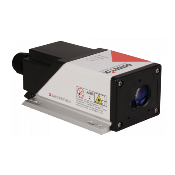
SWISS PRECISION
LASER DISTANCE SENSORS
Application Note
AN2041
D-Series
Getting started with EtherNet/IP™
V1.00
Please check
www.dimetix.com
for the latest version
Abstract
This Application Note describes a simple example of use to get started with the EtherNet/IP™ interface of the Dimetix
D-Series laser distance sensors.
This Application Note is provided as is without any warranty for any problems this sample may cause.
File: AN2041 Getting started with_EtherNetIP V100.odt
Dimetix AG
Degersheimerstr. 14
9100 Herisau
Switzerland
Phone +41 71 353 00 00
Fax +41 71 353 00 01
info@dimetix.com
www.dimetix.com
•
•
•
•
•
•
•
Advertisement
Table of Contents

Related Manuals for Dimetix D Series


Summary of Contents for Dimetix D Series
- Page 1 Abstract This Application Note describes a simple example of use to get started with the EtherNet/IP™ interface of the Dimetix D-Series laser distance sensors. This Application Note is provided as is without any warranty for any problems this sample may cause.
-
Page 2: Table Of Contents
SWISS PRECISION LASER DISTANCE SENSORS Table of content 1 Document scope .........................................3 2 Safety instructions ......................................3 3 Introduction ........................................4 3.1 Overview........................................4 3.2 Prerequisites – Hardware & Software.................................4 4 Description file (EDS) ......................................5 5 Module configuration ......................................5 5.1 New / Add module.....................................5 5.2 Connection configuration...................................6 5.3 RPI configuration......................................7 6 Connection established .......................................8... -
Page 3: Document Scope
LASER DISTANCE SENSORS 1 Document scope 1 Document scope This document covers an Application Note written for the Dimetix D-Series Laser Distance Sensors with EtherNet/IP™ interface. The following topics are discussed: • Safety instructions • Application Note descriptions 2 Safety instructions This Application Note is written for qualified system integrators to help doing an application specific sensor configuration. -
Page 4: Introduction
Dimetix laser distance sensor and the safe values of the device are activated. The “RUN/REM/PROG" switch must be set to RUN to set the RUN flag in the Run/Idle header of the process data frames. Otherwise the Dimetix laser distance sensor does not take over the output data and the safe values of the device are activated. -
Page 5: Description File (Eds)
Figure 2: Rockwell Automation's EDS Wizard. Selection and installation of the EDS source file. After this step the Dimetix Laser Distance Sensor will be available in the module catalog of the Logix Designer software as a EtherNet/IP™ module. For details see the next chapter 5. -
Page 6: Connection Configuration
LASER DISTANCE SENSORS 5 Module configuration Figure 3: Controller Organizer – Context menu (right click) –› New Module... to add a new module to the network Figure 4: Module type selection – Select the corresponding module type, in this example “Laser Distance Sensor DX400”. Optional use the filter possibility to filter the available module types. -
Page 7: Rpi Configuration
LASER DISTANCE SENSORS 5 Module configuration Figure 5: Module properties (General tab) – Change the connection type to “I/O Basic” (Exclusive-Owner connection). Module Properties –› General tab –› Change... button –› Selection of “I/O Basic”. 5.3 RPI configuration The configuration of the process data interval time for the selected Laser Distance Sensor is available in the module properties configuration windows (see figure 6 for details). -
Page 8: Connection Established
LASER DISTANCE SENSORS 5 Module configuration Figure 6: Module properties (Connection tab) – Change the Requested Packet Interval (RPI) of the cyclic process data. In this example: 1 ms. 6 Connection established The establishment of a connection can be achieved by selecting the online mode. This can be done according the details in figure 7. Figure 7: Connection establishment –... -
Page 9: Parameter
LASER DISTANCE SENSORS 6 Connection established Figure 8: Module properties – Connection status: “Running” (for established connection) 7 Parameter The parameter table in figure 9 is continuously updated with sensor data as soon as the connection is established (Online mode). This will be done automatically with the acyclic EtherNet/IP™... -
Page 10: Controller Tags - Input / Output
DX400:I (Input) and DX400:O Output) tags will be done. The available input tags are shown in figure 11 and the available output tags in figure 12. Remark: The Add-On-Profile (AOP) key to unlock additional features is integrated in the EDS file of the Dimetix laser sensor (see figure 10 for this information). No action needs to be taken. -
Page 11: Plc Application
LASER DISTANCE SENSORS 9 Controller tags – All Figure 13: Controller tags – All available tags in the controller. In gray –› Automatically generated tags (DX400:I, DX400:O). In white –› Manually created tags (e.g. Distance_Unit_Read). 10 PLC application 10.1 Main routine In the task tree the “MainRoutine”... -
Page 12: Local Tags
LASER DISTANCE SENSORS 10 PLC application 10.2 Local tags Local tags are temporary variable. In this example the local tags in figure 15 are used for triggering the acyclic services via OSR blocks (for details see chapter 10.4. Figure 15: Main Program – List of local tags used in this example main program routines. 10.3 Measurement control The “Measurement_Control”, a part of the cyclic process output data, is used to start and stop the distance measurements of the laser distance sensor. - Page 13 LASER DISTANCE SENSORS 10 PLC application Message configuration Descriptions Message Type CIP Generic as default. Service Type Service type e.g. “Get Attribute Single” for acyclic read service or “Set Attribute Single” for acyclic write service. Class, Instance, Attribute EtherNet/IP™ access information of the corresponding parameter. See the Technical Reference Manual of the Industrial Ethernet for this information.
- Page 14 LASER DISTANCE SENSORS 10 PLC application Figure 19: Message configuration (MSG) – Tag tab: No configuration used (in this example) In of case of an error the Error Code and Extended Error Code in the .ER tag of the corresponding parameter must be evaluated. See figure 20 for more details.
-
Page 15: Reset Acyclic Values
LASER DISTANCE SENSORS 10 PLC application 10.4.4 Distance unit – Read The routines in figure 22 show the acyclic read service (MSG) to read the distance unit of the module. This read service can be triggered with the associated controller tag “Distance_Unit_Read_Ctrl”. So that this acyclic message instruction is only done once, the OSR (One Shot Rising) instruction block is used in addition. -
Page 16: Logix Designer
LASER DISTANCE SENSORS 11 IP parameter 11.1 Logix Designer The IP parameter can be changed according figure 25 in the module properties. There will be a warning to indicate that the access to the device will be lost. Remark: After the change of the IP parameter, the access to the device will then be lost because of different IP parameter in the PLC project and the device. - Page 17 LASER DISTANCE SENSORS 11 IP parameter The IP parameter can be simple changed with this tool. For details how to do this, see figure 27 and 28. Figure 27: RSLinx Classic Lite tool – Context menu of the desired device –› Module Configuration: Module configuration window. Figure 28: RSLinx Classic Lite tool –...
- Page 18 LASER DISTANCE SENSORS 11 IP parameter Figure 29: RSLinx Classic Lite tool – Network scan: Display all available and no longer available scanners and adapters. In addition to the configuration of the IP parameter, the network configuration type can also be configured. Available network configuration types: Static, DHCP and BOOTP.
-
Page 19: Glossary
LASER DISTANCE SENSORS 12 Glossary 12 Glossary Add On Profile key to unlock additional features (integrated in the EDS file). BOOTP / DHCP Different network configuration type: Bootstrap Protocol (BOOTP) and Dynamic Host Configuration Protocol (DHCP). Electronic Data Sheet file. Describes the properties of an adapter or scanner device. EtherNet/IP™... - Page 20 Customers should obtain the latest relevant information before placing orders and should verify that such information is up to date and complete. All products are sold subject to Dimetix terms and conditions of sale supplied at the time of order acknowledgment.
Need help?
Do you have a question about the D Series and is the answer not in the manual?
Questions and answers