Advertisement
Quick Links
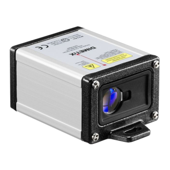
Laser Distance Sensors
Manual EDS-C
Congratulations on the purchase of your Dimetix EDS-C distance sensor.
1
Overview
2
Dimensions
Laser Beam
21.3
33.44
62
CAUTION
Use of controls or adjustments or performance of
procedures other than those specified herein may result in
hazardous radiation exposure.
3
First Start-Up
To configure the EDS-C, you need the sensor, a connection cable (see
chapter 11 accessories), a 24VDC power supply and the easy to apply "EDS
Start-Up" Software. The "EDS Start-Up" Software for configuration is
available as free ware on our web-page:
Connect the EDS-C to a PC/Laptop using the RS-232 interface, define and
download your configuration and install the sensor in your application.
4
Connection for configuration
We propose to use our standard configuration cable (see Accessories).
Please note, that some "USB to RS-232 converter" can cause problems.
2
Rx
3
Tx
5
Gnd
9 pin D-Sub
female
Start-Up Software
www.dimetix.com
Measuring reference
M12 5pole
Sensor Plug
All dimensions in mm
www.dimetix.com
5
Tx (RS-232)
4
Rx (RS-232)
3
Analog Out (mA)
2
GND
1
Vcc
M12 5-Pin:
(black) Rx 4
(brown) Vcc 1
-
-
+
24VDC
5
EDS Start-Up Software
V1.4
On the sensor you can configure the following by using the "EDS Start-Up"
Software" (
6
Configuration of the EDS-C
To achieve the maximum possible analog output accuracy, we suggest to
configure the span as short as possible. For example, if you measure
distances of 12 to 19 meters, you should configure a span of 10m to 20m
(corresponding to 0/4...20mA)
Sensor Configuration:
minimum output current
Error output current
minimum Distance
maximum Distance
Measurement sample rate
Command Set (if not using the free "EDS Start-Up" Software)
Baud Rate: 19'200; Data Bits: 7; Parity: even; Stopbits: 1
Command Terminator is: <CR> <LF> (Carriage return, Line feed)
The first two characters in the commands are s0 (s, zero)
For further information about the command-set read the COM- trace in
our "EDS Start-Up" Software.
7
Connection diagram EDS-C to control unit
Customers
Control Unit
Load
0...20mA
Input
The load resistor must be less than 500Ω for a power supply of 24V. If the
power supply is less then 24V, the max. load resistor is reduced. At 12V the
load resistor must be less than 350Ω.
8
Measuring conditions
The EDS is an optical instrument, whose operation is influenced by
environmental conditions. Therefore, the measuring range may vary. The
following conditions may influence speed and range of the measurements:
Key
Target
surface
EDS
Airborne
particles
3 AO (blue)
5 Tx (grey)
2 Gnd (white)
Sunshine
www.dimetix.com )
Default sensor
configuration
4mA
0mA
0mm
10'000mm
1s
for configuration
0/4...20mA current loop
+
-
24VDC
Factors increasing range
and/or distance
Bright and/or reflective
surfaces such as our target
plates
Clean air
Darkness
Configuration
limits
0 or 4mA
0...20mA
0...30'000mm
1000...30'000mm
0...65'000s
5
Tx (RS-232)
{
4
Rx (RS-232)
3
Analog Out (mA)
2
GND
EDS
1
Vcc
M12 5-Pin:
3 AO (blue)
(black) Rx 4
5 Tx (grey)
(brown) Vcc 1
2 Gnd (white)
Factors reducing range
and/or distance
Matt and/or dark surfaces
green / blue / black
surfaces
Dust, fog, heavy rainfall,
heavy snowfall
Bright sunshine on the
target
Advertisement

Related Manuals for Dimetix EDS-C


Summary of Contents for Dimetix EDS-C
- Page 1 0/4...20mA current loop Load First Start-Up 0...20mA Input To configure the EDS-C, you need the sensor, a connection cable (see M12 5-Pin: 3 AO (blue) chapter 11 accessories), a 24VDC power supply and the easy to apply "EDS (black) Rx 4...
- Page 2 Operating Temperature -10 °C to +50 °C If the EDS-C is part of a system, the manufacturer of such a system is Storage Temperature -40 °C to +70 °C responsible for all safety-related issues, such as the manual, labeling and Environment Humidity 0...80%RH non-condensing;...
Need help?
Do you have a question about the EDS-C and is the answer not in the manual?
Questions and answers