Table of Contents
Advertisement
Quick Links
Advertisement
Chapters
Table of Contents

Related Manuals for Ditch Witch RT120


Summary of Contents for Ditch Witch RT120
- Page 1 RT120 Operator’s Manual Issue 1.0 ® 053-2697 Original Translation...
-
Page 2: Table Of Contents
RT120 Operator’s Manual Overview - 1 Overview Chapter Contents Serial Number Location ..... . 2 Intended Use ....... 3 Equipment Modification . -
Page 3: Serial Number Location
RT120 Operator’s Manual Overview - 2 Serial Number Location Serial Number Location Record serial numbers and date of purchase in spaces provided. RT120 (1) and engine serial numbers (2) are located as shown. t41om001w.eps Date of manufacture Date of purchase... -
Page 4: Intended Use
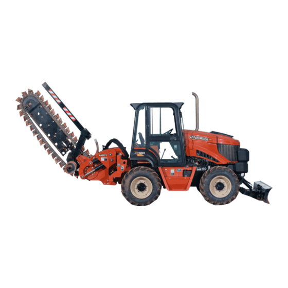
RT120 Operator’s Manual Overview - 3 Intended Use Intended Use The RT120 is a riding trencher designed to install buried service lines of various sizes using a variety of Ditch Witch attachments. Attachment Max. width/diameter Max. depth* H910 trencher 24” (610 mm) 100”... -
Page 5: Unit Components
RT120 Operator’s Manual Overview - 4 Unit Components Unit Components t41om002w.eps 1. Rollover Protective Structure (ROPS) 4. Engine compartment 2. Operator station 5. Backfill blade (optional) 3. Control console WARNING: The protection offered by the Rollover Protective System (ROPS) will be impaired if it has been subjected to any modification, structural damage, or has been involved in an overturn accident. -
Page 6: Operator Orientation
RT120 Operator’s Manual Overview - 5 Operator Orientation Operator Orientation 1. Front of unit 3. Rear of unit 2. Right of unit 4. Left of unit Right and left sides of machine are determined by facing front of unit while seated at the controls. - Page 7 RT120 Operator’s Manual Overview - 6 About This Manual...
-
Page 8: Foreword
If you sell your equipment, be sure to give this manual to the new owner. If you need a replacement copy, contact your Ditch Witch dealer. If you need assistance in locating a dealer, visit our website at www.ditchwitch.com or write to the following address: The Charles Machine Works, Inc. - Page 9 RT120 Operator’s Manual Foreword - 8 RT120 Tier 4i Operator’s Manual Issue number 1.0/OM-09/13 Part number 053-2697 Copyright 2013 by The Charles Machine Works, Inc. , Ditch Witch, CMW, and Roto Witch are registered trademarks of The Charles Machine Works, Inc.
- Page 10 RT120 Operator’s Manual Contents - 9 Contents Overview machine serial number, information about the type of work this machine is designed to perform, basic machine components, and how to use this manual Foreword part number, revision level, and publication date of this manual, and factory contact...
- Page 11 RT120 Operator’s Manual Contents - 10 Drill procedures for drilling procedures for sawing Systems and Equipment chain, teeth, sprockets, and optional equipment Complete the Job procedures for backfilling and restoring the jobsite and rinsing and storing equipment Service service intervals and instructions for this machine including lubrication, replacement...
-
Page 12: Safety
RT120 Operator’s Manual Safety - 11 Safety Chapter Contents Guidelines ....... . 12 Emergency Procedures . -
Page 13: Guidelines
Use equipment carefully. Stop operation and investigate anything that does not look or feel right. • Do not operate unit where flammable gas may be present. • Contact your Ditch Witch dealer if you have any question about operation, maintenance, or equipment use. • Complete the equipment checklist located at www.ditchwitch.com/resources/safety. -
Page 14: Emergency Procedures
RT120 Operator’s Manual Safety - 13 Emergency Procedures Emergency Procedures Jobsite hazards could cause death or serious injury. Use correct equipment and work methods. Use and maintain proper safety equipment. Before operating any equipment, review emergency procedures and check that all safety precautions have been taken. -
Page 15: If An Electric Line Is Damaged
RT120 Operator’s Manual Safety - 14 Emergency Procedures If an Electric Line is Damaged If you suspect an electric line has been damaged and you are near pedestrian unit, DO NOT MOVE and do not touch unit. Take the following actions. The order and degree of action will depend upon the situation. -
Page 16: If A Fiber Optic Cable Is Damaged
RT120 Operator’s Manual Safety - 15 Emergency Procedures If a Fiber Optic Cable is Damaged Do not look into cut ends of fiber optic or unidentified cable. Vision damage can occur. If Machine Catches on Fire Perform emergency shutdown procedure and then take the following actions. The order and degree of action will depend on the situation. - Page 17 RT120 Operator’s Manual Safety - 16 Emergency Procedures CMW®...
-
Page 18: Safety Alert Classifications
RT120 Operator’s Manual Safety - 17 Safety Alert Classifications Safety Alert Classifications These classifications and the icons defined on the following pages work together to alert you to situations which could be harmful to you, jobsite bystanders or your equipment. When you see these words and icons in the book or on the machine, carefully read and follow all instructions. -
Page 19: Machine Safety Alerts
RT120 Operator’s Manual Safety - 18 Machine Safety Alerts Machine Safety Alerts Runaway possible. Machine could run over you or others. Learn how to use all controls. Start and operate only from operator’s position. Fall possible. Riders can fall from machine and be injured or killed. -
Page 20: Attachment Safety Alerts
RT120 Operator’s Manual Safety - 19 Machine Safety Alerts Tiedown location. See Transport chapter for more information. Rollover possible. If machine rolls over, you could be thrown from seat and killed or crushed. Wear seat belt. Read operator’s manual. Know how to use all controls before operating machine. - Page 21 RT120 Operator’s Manual Safety - 20 Attachment Safety Alerts Attachment Safety Alerts A920 Moving parts could cut off hand or foot. Stay away. Crushing weight could cause death or serious injury. Use proper procedures and equipment or stay away. CMW®...
- Page 22 RT120 Operator’s Manual Safety - 21 Attachment Safety Alerts H910 Moving digging teeth will cause death or serious injury. Trench cave-in can cause you to fall. Stay away. Tiedown location. See Transport chapter for more information. Moving digging teeth will cause death or serious injury.
- Page 23 RT120 Operator’s Manual Safety - 22 Attachment Safety Alerts H911 Moving digging teeth will cause death or serious injury. Trench cave-in can cause you to fall. Stay away. Lift point. See Transport chapter for more information. Moving parts could cut off hand or foot. Stay away.
- Page 24 RT120 Operator’s Manual Safety - 23 Attachment Safety Alerts Moving digging teeth will cause death or serious injury. Trench cave-in can cause you to fall. Stay away. CMW®...
- Page 25 RT120 Operator’s Manual Safety - 24 Attachment Safety Alerts H932 Tiedown location. See Transport chapter for more information. Moving parts could cut off hand or foot. Stay away. Crushing weight could cause death or serious injury. Use proper procedures and equipment or stay away.
- Page 26 RT120 Operator’s Manual Safety - 25 Attachment Safety Alerts H952 Moving digging teeth will cause death or serious injury. Trench cave-in can cause you to fall. Stay away. Tiedown location. See Transport chapter for more information. Lift point. See Transport chapter for more information.
- Page 27 RT120 Operator’s Manual Safety - 26 Attachment Safety Alerts H1140 Moving parts could cut off hand or foot. Stay away. Tiedown location. See Transport chapter for more information. Lift point. See Transport chapter for more information. Flying objects may cause injury. Wear hard hat and safety glasses.
- Page 28 RT120 Operator’s Manual Safety - 27 Attachment Safety Alerts Moving digging teeth will cause death or serious injury. Trench cave-in can cause you to fall. Stay away. RC120 Lift point. See Transport chapter for more information. Crushing weight could cause death or serious injury.
- Page 29 RT120 Operator’s Manual Safety - 28 Attachment Safety Alerts CMW®...
-
Page 30: Controls
RT120 Operator’s Manual Controls - 29 Controls Chapter Contents Center Console ......30 Graphic Display. -
Page 31: Center Console
RT120 Operator’s Manual Controls - 30 Center Console Center Console t41om004w.eps 1. Auxiliary power outlet 8. Reel winder mode selector switch* 2. Horn switch 9. Ignition key switch 3. Engine override switch 10. Ground drive foot control 4. Axle lock switch 11. - Page 32 RT120 Operator’s Manual Controls - 31 Center Console Item Description Notes 1. Auxiliary outlet Provides power for other Power output is 12V, 10A. equipment. c00ic179h.eps 2. Horn switch To sound horn, press. c00ic044h.eps 3. Engine override switch For engine override, press.
- Page 33 RT120 Operator’s Manual Controls - 32 Center Console Item Description Notes 5. Graphic display Graphic symbols are See more information in “Graphic displayed for indicators and Display” on page 34. conditions previously shown with gauges. c00ic604w.eps 6. Ground drive motor...
- Page 34 RT120 Operator’s Manual Controls - 33 Center Console Item Description Notes 9. Ignition switch To start engine, insert key and IMPORTANT: If engine does not start turn clockwise. on first attempt, check that all interlock requirements have been To stop engine, turn met, return switch to STOP, and try counterclockwise.
-
Page 35: Graphic Display
RT120 Operator’s Manual Controls - 34 Graphic Display Graphic Display AM/PM x100 0.0 v 0 PSI 0.0 H t41om040w.eps The graphic display module shows engine RPM and has icons for other functions. Soft keys allow the operator to toggle between various screens and functions. - Page 36 RT120 Operator’s Manual Controls - 35 Graphic Display Item Description Notes Operator presence Indicates operator presence and start interlock condition. c00ic001w.eps Fuel level Displays fuel level and percentage. c00ic003w.eps Battery voltage Displays battery voltage. c00ic008w.eps Day/Night mode Indicates selected mode.
- Page 37 RT120 Operator’s Manual Controls - 36 Graphic Display Item Description Notes Engine hours Displays engine hours. 0.0 H c00ic020w.eps Engine oil pressure Displays engine oil pressure. Engine coolant temperature Displays coolant temperature. c00ic004w.eps Axle lock Displays status of axle differential lock.
- Page 38 RT120 Operator’s Manual Controls - 37 Graphic Display Item Description Notes Ground drive speed/ Displays ground drive direction direction of travel, and speed as a percentage. c00ic006w.eps Ground drive gear indicator Displays selected gear in center of icon. c00ic009w.eps Cruise control indicator Displays cruise mode status.
- Page 39 RT120 Operator’s Manual Controls - 38 Graphic Display Item Description Notes Hydraulic filter restriction Displays restriction status. indicator Hydraulic fluid high Displays hot fluid status. temperature indicator c00ic037t.eps Menu indicator Displays menu icon over key c00ic031w.eps...
- Page 40 RT120 Operator’s Manual Controls - 39 Graphic Display Main Menu SYSTEM USER GAUGE DIGNOSTICS SETTINGS SETTINGS DISPLAY t33om093w.eps Press the center soft key to display the main menu screen, which has icons for other functions. Soft keys below on screen icons allow the operator to toggle between various screens and functions.
- Page 41 Diagnostics Displays interlock icons and Note: If diagnostic codes are diagnostic codes, if any. displayed, contact your Ditch Witch dealer. Press soft key below on screen icons to return to main menu or gauge display. c00ic018w.eps...
- Page 42 RT120 Operator’s Manual Controls - 41 Graphic Display System Settings SYSTEM SETTINGS Component VERSION Part No. Application 10155 Release 78333159 10081 Release 78333166 Bootloader 10146 Release 78333156 Configuration Beta RT120T4i Copyright 2012 The Charles Machine Works Back t41om005w.eps Item Description...
- Page 43 RT120 Operator’s Manual Controls - 42 Graphic Display User Settings USER SETTINGS Ambient Light Brightness 100% Units USA Standard Language English Back Save Reset t33om092w.eps Item Description Notes Back Press soft key below this icon Press center soft key to display gauge to return to previous screen.
- Page 44 RT120 Operator’s Manual Controls - 43 Graphic Display Item Description Notes Save Press soft key below this icon to save settings. c00ic013w.eps Reset Press soft key below this icon to return to default settings. c00ic014w.eps Day/Night Press soft key below this icon to select day or night mode.
- Page 45 RT120 Operator’s Manual Controls - 44 Graphic Display Diagnostics GAUGE MAIN MENU DISPLAY t37om044w.eps Note: If diagnostic codes are displayed, contact your Ditch Witch dealer. Item Description Notes Attachment Neutral Indicates attachment controls in neutral position. c00ic021w.eps...
- Page 46 RT120 Operator’s Manual Controls - 45 Graphic Display Item Description Notes Operator Presence Indicates operator presence for start interlock status. c00ic001w.eps Ground Drive Neutral Indicates ground drive controls in neutral position. c00ic022w.eps Main Menu Press soft key below this icon Press center soft key to display gauge to return to previous screen.
- Page 47 RT120 Operator’s Manual Controls - 46 Graphic Display Item Description Notes Engine stop Flashing icon indicates Switch must be raised (reset) to allow engine stop switch has been engine starting. pressed from backhoe operator’s station. c00ic649w.eps...
-
Page 48: Right Console
RT120 Operator’s Manual Controls - 47 Right Console Right Console t37om005w.eps 1. Backfill blade lift/tilt function control 4. Frame tilt control* 2. Rear steer control* 5. Throttle 3. Rear steer manual/auto control* *option... - Page 49 RT120 Operator’s Manual Controls - 48 Right Console Item Description Notes 1. Backfill blade lift/tilt Backfill blade mode: Reel winder mode selector switch on function control center console changes function to • To lower, move forward. control reel winder arm lift and winder direction.
- Page 50 RT120 Operator’s Manual Controls - 49 Item Description Notes 4. Frame tilt control To tilt left, press left. To tilt right, press right. c00ic626w.eps 5. Throttle To increase speed, move forward. To decrease speed, move rearward.
-
Page 51: Left Console
RT120 Operator’s Manual Controls - 50 Left Console Left Console t37om006w.eps 1. Parking brake control 1. Parking brake control To set brake, pull handle up. Engaged parking brake disables ground drive. To release brake, push handle down. - Page 52 RT120 Operator’s Manual Controls - 51 Rear Console Rear Console t37om007w.eps 1. Cruise control selector switch 2. Cruise control rpm dial control 1. Cruise control selector To turn on, press top. Switch Turn on cruise control only when: indicator and display should indicate that cruise mode is •...
- Page 53 RT120 Operator’s Manual Controls - 52 2. Cruise control rpm dial To decrease engine load This typically decreases engine load control while using cruise control, temporarily. turn clockwise. To increase engine load while This typically increases engine load using cruise control, turn temporarily.
-
Page 54: Seat Console
RT120 Operator’s Manual Controls - 53 Seat Console Seat Console j26rg157h.jpg 1. Ground drive speed/direction control 3. Ground drive gear selector 2. Attachment speed/direction control Item Description Notes 1. Ground drive speed/ To go faster in either NOTICE: Control does not... - Page 55 RT120 Operator’s Manual Controls - 54 Seat Console Item Description Notes 2. Attachment speed/ To go faster in either NOTICE: Control does not direction control direction, move farther from automatically return to neutral. neutral. To stop, return to center. c00ic632w.eps 3.
-
Page 56: Seat Deck
RT120 Operator’s Manual Controls - 55 Seat Deck Seat Deck t33om003w.eps t33om003w.eps 1. Seat belt 4. Seat height adjustment lock 2. Armrest adjustment control 5. Seat pivot control 3. Seat slide control Item Description Notes 1. Seat belt To fasten, insert latch into buckle. - Page 57 RT120 Operator’s Manual Controls - 56 Seat Deck Item Description Notes 3. Seat slide control To slide seat forward or backward, pull, then adjust seat. To lock seat in place, release. 4. Seat height adjustment To lock seat height, turn lock clockwise.
-
Page 58: Trencher Controls
RT120 Operator’s Manual Controls - 57 Trencher Controls Trencher Controls t37om008w.eps 1. Trencher slide control* 3. Boom lift control 2. Trench cleaner lift control* *optional Item Description Notes 1. Trencher slide control To slide trencher right, push. (H911 only) To slide trencher left, pull. - Page 59 RT120 Operator’s Manual Controls - 58 Trencher Controls Item Description Notes 2. Trench cleaner lift To lower, push. control To raise, pull. 3. Boom lift control To lower, push. To raise, pull.
-
Page 60: Plow Controls
RT120 Operator’s Manual Controls - 59 Plow Controls Plow Controls t37om009w.eps 1. Plow swing control 3. Plow lift control 2. Blade steer control 4. Stow lock control Item Description Notes 1. Plow swing control To swing left, pull. NOTICE: To swing right, push. - Page 61 RT120 Operator’s Manual Controls - 60 Plow Controls Item Description Notes 2. Blade steer control To steer right, push. To steer left, pull. c00ic203h.eps 3. Plow lift control To raise, pull. NOTICE: To lower, push. • If soil conditions allow, operate in float position.
-
Page 62: Combo Controls
RT120 Operator’s Manual Controls - 61 Combo Controls Combo Controls t37om010w.eps 1. Plow swing control 4. Boom lift control 2. Blade steer control 5. Plow stow lock control 3. Plow lift control 6. Trench / Plow switch Item Description Notes 1. - Page 63 RT120 Operator’s Manual Controls - 62 Combo Controls 2. Blade steer control To steer right, push. To steer left, pull. c00ic203h.eps 3. Plow lift control To raise, pull. NOTICE: To lower, push. • If soil conditions allow, operate in float position.
- Page 64 RT120 Operator’s Manual Controls - 63 Combo Controls 6. Trench / Plow switch To trench, set switch to trench position. To plow, set switch to plow position.
-
Page 65: Backhoe Console
RT120 Operator’s Manual Controls - 64 Backhoe Console Backhoe Console t37om046w.eps 1. Remote backfill blade control* 7. Swing lock pin 2. Left stabilizer control 8. Ground drive switch 3. Boom/Swing control 9. Remote engine stop switch 4. Remote throttle control switch 10. - Page 66 RT120 Operator’s Manual Controls - 65 Backhoe Console Item Description Notes 1. Remote backfill blade To lower, push. control To raise, pull. 2. Left stabilizer control To lower, push out. To raise, pull in. 3. Boom/Swing control To swing boom left, move left.
- Page 67 RT120 Operator’s Manual Controls - 66 Backhoe Console Item Description Notes 5. Remote throttle enable To enable remote throttle Note: This switch must be returned to control, press top. the OFF position for normal throttle control at tractor. To disable remote throttle control, press bottom.
- Page 68 RT120 Operator’s Manual Controls - 67 Backhoe Console Item Description Notes 9. Remote engine stop Press to stop engine For normal engine shutdown, use switch immediately. ignition switch. Display icon will flash. Note: This switch must be returned to the UP position to allow engine restarting.
-
Page 69: Saw Controls
RT120 Operator’s Manual Controls - 68 Saw Controls Saw Controls t37om045w.eps 1. Saw slide control 2. Saw lift control Item Description Notes 1. Saw slide control To slide saw right, push. To slide saw to center, pull. - Page 70 RT120 Operator’s Manual Controls - 69 Item Description Notes 2. Saw lift control To lower, push. To raise, pull. c00ic209h.eps...
-
Page 71: Drill Controls
RT120 Operator’s Manual Controls - 70 Drill Controls Drill Controls t33om063w.eps 1. Drilling attachment control 2. Drilling attachment Item Description Notes 1. Drilling attachment To rotate clockwise, press IMPORTANT: Always rotate control bore. clockwise during drilling and backreaming. Rotate To rotate counterclockwise, counterclockwise only to dislodge a press reverse. -
Page 72: Battery Disconnect
RT120 Operator’s Manual Controls - 71 Battery Disconnect Battery Disconnect t41om007w.eps 1. Battery disconnect switch Item Description Notes 1. Battery disconnect To connect, move left. NOTICE: Do not operate battery switch switch with engine running. To disconnect, move right. c00ic063t.eps... - Page 73 RT120 Operator’s Manual Controls - 72...
-
Page 74: Operation Overview
RT120 Operator’s Manual Operation Overview - 73 Operation Overview Chapter Contents Planning........74 Trenching. - Page 75 RT120 Operator’s Manual Operation Overview - 74 Planning Planning 1. Gather information about jobsite. See page 78. 2. Inspect jobsite. See page 79. 3. Classify jobsite. See page 80. 4. Select chain and teeth to match your soil type, if necessary. See page 148 5.
- Page 76 RT120 Operator’s Manual Operation Overview - 75 Digging with Backhoe 4. Begin drilling. See page 133. 5. Use drill string guide as needed. See page 134. 6. Add rod. See page 135. 7. Backream. See page 135. 8. Shut down tractor. See page 88.
- Page 77 RT120 Operator’s Manual Operation Overview - 76 Leaving Jobsite...
-
Page 78: Prepare
RT120 Operator’s Manual Prepare - 77 Prepare Chapter Contents Gather Information ......78 • Review Job Plan ......... . 78 •... -
Page 79: Gather Information
RT120 Operator’s Manual Prepare - 78 Gather Information Gather Information A successful job begins before you dig. The first step in planning is reviewing information already available about the job and jobsite. Review Job Plan Review blueprints or other plans. Check for information about existing or planned structures, elevations, or proposed work that may be taking place at the same time. -
Page 80: Inspect Site
RT120 Operator’s Manual Prepare - 79 Inspect Site Inspect Site Inspect jobsite before transporting equipment. Check for the following: • changes in elevation such as hills or other open trenches • obstacles such as buildings, railroad crossings, or streams •... -
Page 81: Classify Jobsite
RT120 Operator’s Manual Prepare - 80 Classify Jobsite Classify Jobsite Inspect Jobsite • Follow U.S. Department of Labor regulations on excavating and trenching (Part 1926, Subpart P) and other similar regulations. • Contact your local One-Call (811 in USA) or the One-Call referral number (888-258-0808 in USA and Canada) to have underground utilities located before digging. -
Page 82: Apply Precautions
RT120 Operator’s Manual Prepare - 81 Classify Jobsite Apply Precautions Once classified, precautions appropriate for jobsite must be taken. Electric Jobsite Precautions Use one or both of these methods. • Expose line by careful hand digging or soft excavation. •... -
Page 83: Check Supplies And Prepare Equipment
RT120 Operator’s Manual Prepare - 82 Check Supplies and Prepare Equipment Check Supplies and Prepare Equipment Supplies • fuel • keys • personal protective equipment, such as hard hat and safety glasses Fluid Levels • fuel • hydraulic fluid •... -
Page 84: Drive
RT120 Operator’s Manual Drive - 83 Drive Chapter Contents Start Unit ....... . . 84 Drive . -
Page 85: Start Unit
RT120 Operator’s Manual Drive - 84 Start Unit Start Unit Before operating tractor, read engine manufacturer’s starting and operating instructions. Follow instructions for new engine break-in. Read operator’s manual. Know how to use all controls before operating machine. When you see this sign on the machine or in the manual, read it and use caution. - Page 86 RT120 Operator’s Manual Drive - 85 Start Unit 1. Fasten and adjust seat belt. 2. Check that ground drive control and attachment speed/direction control are in neutral. 3. Move throttle to idle. 4. Verify that parking brake is engaged. 5. Turn ignition switch to the run position (key on, engine off). Cold start wait indicator will light (if equipped).
-
Page 87: Drive
RT120 Operator’s Manual Drive - 86 Drive Drive General Operation Moving traffic – hazardous situation. Death or serious injury could result. Avoid moving vehicles, wear high visibility clothing, post appropriate warning signs. To help avoid injury: • Drive carefully in congested areas. Know machine’s clearance and turning radius. -
Page 88: Safe Slope Operation
RT120 Operator’s Manual Drive - 87 Drive Safe Slope Operation Tipover possible. Machine can tip over and crush you. To help avoid injury: • Always operate with heavy end uphill. • Drive cautiously at all times. • Never jerk control levers. Use a steady even motion. -
Page 89: Shut Down
RT120 Operator’s Manual Drive - 88 Shut Down Shut Down 1. When job is complete, move ground drive control to neutral. 2. Engage parking brake and verify parking brake indicator is on. 3. Lower all attachments to ground and let machine idle for three minutes to cool. -
Page 90: Transport
RT120 Operator’s Manual Transport - 89 Transport Chapter Contents Lift ........90 •... -
Page 91: Lift
RT120 Operator’s Manual Transport - 90 Lift Lift Crushing weight. If load falls or moves it could kill or crush you. Use proper procedures and equipment or stay away. Read operator’s manual. Know how to use all controls before operating machine. - Page 92 RT120 Operator’s Manual Transport - 91 Lift Centerline Trencher Use crane capable of supporting the equipment's size and weight. See “Specifications” on page 197 or measure and weigh equipment before lifting. Traversing Trencher Use crane capable of supporting the equipment's size and weight. See “Specifications”...
- Page 93 RT120 Operator’s Manual Transport - 92 Lift Plow Use crane capable of supporting the equipment's size and weight. See “Specifications” on page 197 or measure and weigh equipment before lifting. Reel Carrier Use crane capable of supporting the equipment's size and weight. See page 197 or...
-
Page 94: Tie Down
RT120 Operator’s Manual Transport - 93 Tie Down Tie Down Read operator’s manual. Know how to use all controls before operating machine. When you see this sign on the machine or in the manual, read it and use caution. Your safety is at stake. - Page 95 RT120 Operator’s Manual Transport - 94 Tie Down Traversing Trencher Lower trencher to trailer deck and chain at attachment frame and through boom. Make sure chains are tight before transporting. Combo Lower attachment to trailer deck and chain at attachment frame and vibrator box. Make sure chains are tight before transporting.
- Page 96 RT120 Operator’s Manual Transport - 95 Tie Down Plow Lower plow to trailer deck and chain at attachment frame and vibrator box. Make sure chains are tight before transporting. NOTICE: • Engage attachment stow lock and swing lock devices in addition to securing at tiedowns.
-
Page 97: Haul
RT120 Operator’s Manual Transport - 96 Haul Haul Read operator’s manual. Know how to use all controls before operating machine. When you see this sign on the machine or in the manual, read it and use caution. Your safety is at stake. - Page 98 RT120 Operator’s Manual Transport - 97 Haul Load Crushing weight. If load falls or moves it could kill or crush you. Use proper procedures and equipment or stay away. To help avoid injury: • Attach trailer to tow vehicle before loading or unloading.
- Page 99 RT120 Operator’s Manual Transport - 98 Haul Unload Crushing weight. If load falls or moves it could kill or crush you. Use proper procedures and equipment or stay away. NOTICE: • Attach trailer to tow vehicle before loading or unloading.
-
Page 100: Tow
RT120 Operator’s Manual Transport - 99 Read operator’s manual. Know how to use all controls before operating machine. When you see this sign on the machine or in the manual, read it and use caution. Your safety is at stake. - Page 101 RT120 Operator’s Manual Transport - 100...
-
Page 102: Trench
RT120 Operator’s Manual Trench - 101 Trench Chapter Contents Setup ........102... - Page 103 Your safety is at stake. NOTICE: The RT120 is programmed to operate with the original attachment (trencher or plow) configuration. If you change attachments, contact your Ditch Witch dealer to make sure the electronic programming is updated.
- Page 104 RT120 Operator’s Manual Trench - 103 Setup 1. If using optional trench cleaner, remove bolt installed for transport. 2. Fasten and adjust seat belt. 3. Start tractor. See page 84 for start-up procedures. 4. Drive to starting point. Move in line with planned trench. See page 86 for driving procedures.
- Page 105 RT120 Operator’s Manual Trench - 104 Operation Operation Read operator’s manual. Know how to use all controls before operating machine. When you see this sign on the machine or in the manual, read it and use caution. Your safety is at stake.
- Page 106 RT120 Operator’s Manual Trench - 105 Operation Start Trench 1. Lower backfill blade, if equipped, to reduce shock when trenching begins. 2. If equipped with combo, set trench/plow switch to the trench position. 3. Move attachment speed/direction control to desired speed. DIGGING CHAIN WILL MOVE.
- Page 107 RT120 Operator’s Manual Trench - 106 Operation Move Forward 1. Raise backfill blade, if equipped. 2. Release parking brake, if set, and verify parking brake indicator is off. 3. If using trench cleaner: • Use ground drive foot control to move forward about 1 foot (30 cm), or until there is enough room for trench cleaner to enter trench.
- Page 108 RT120 Operator’s Manual Trench - 107 Operation Finish Trenching 1. When trench is complete, move ground drive hand control to neutral. 2. Adjust throttle to low idle. 3. Raise boom. 4. As boom clears top of trench, move attachment speed/direction control to neutral.
- Page 109 RT120 Operator’s Manual Trench - 108 Operation...
-
Page 110: Plow
RT120 Operator’s Manual Plow - 109 Plow Chapter Contents Setup ........110 •... -
Page 111: Setup
Do not operate vibrator unless plow is in the ground. • The RT120 is programmed to operate with the original attachment (trencher or plow) configuration. If you change attachments, contact your Ditch Witch dealer to make sure the electronic programming is updated. If you change attachments without updating the electronic programming,... -
Page 112: Position Tractor
RT120 Operator’s Manual Plow - 111 Setup Position Tractor IMPORTANT: If material must be at a constant depth, dig starting and target trenches. 1. Fasten and adjust seat belt. 2. Start tractor. See page 84 for start-up procedures. 3. Drive to starting point. Move in line with planned trench. - Page 113 RT120 Operator’s Manual Plow - 112 Setup To Feed Product IMPORTANT: ROPS-attached cable guide should be a genuine Ditch Witch cable guide manufactured for this purpose. 1. Remove cable guide. 2. Feed cable through tube from top to bottom. 3. Replace cable guide and tighten fasteners.
-
Page 114: Operation
RT120 Operator’s Manual Plow - 113 Operation Operation Read operator’s manual. Know how to use all controls before operating machine. When you see this sign on the machine or in the manual, read it and use caution. Your safety is at stake. - Page 115 RT120 Operator’s Manual Plow - 114 Operation Prepare 1. Fasten and adjust seat belt. 2. Start tractor. 3. Adjust throttle to low idle. 4. Check that ground drive hand and foot controls are in neutral. 5. Release parking brake and verify parking brake indicator is off.
- Page 116 Adjust vibrator speed if ROPS vibrates excessively. Note: In some soil conditions, changing vibrator weights can improve plow performance. Contact your Ditch Witch dealer for details. 8. Check cable for damage during plowing. Run continuity checks on electric cable and check pipe pressure.
- Page 117 RT120 Operator’s Manual Plow - 116 Operation Finish Plowing 1. When installation is complete, move plow swing out of float. 2. With vibrator running, raise plow to ground level. NOTICE: Do not operate vibrator when plow is out of the ground. This will cause excessive vibration resulting in rapid wear, and possible damage to the unit and product being installed.
-
Page 118: Special Plowing
RT120 Operator’s Manual Plow - 117 Operation Special Plowing Your Ditch Witch equipment allows you to plow four ways: normal plowing, offset plowing (1), coordinated plowing (2), and crabbing (3). NOTICE: Oversteering blade may damage blade or cable. Offset Plow Offset plowing can be used to plow next to a road while keeping tires on a more stable surface or in similar conditions. - Page 119 RT120 Operator’s Manual Plow - 118 Operation...
-
Page 120: Reel Carrier
RT120 Operator’s Manual Reel Carrier - 119 Reel Carrier Chapter Contents Setup ........120 •... - Page 121 RT120 Operator’s Manual Reel Carrier - 120 Setup Setup Read operator’s manual. Know how to use all controls before operating machine. When you see this sign on the machine or in the manual, read it and use caution. Your safety is at stake.
- Page 122 RT120 Operator’s Manual Reel Carrier - 121 Setup Reel Position 1. Install reel in one of two positions: • • Ref. Maximum Maximum weight reel length from blade 2500 lb (1134 kg) 84 in (2.13 m) 2200 lb (998 kg) 96 in (2.44 m)
- Page 123 RT120 Operator’s Manual Reel Carrier - 122 Operation Operation 1. Fasten and adjust seat belt. 1. Drive to beginning of planned plow path. 2. Engage parking brake. 3. Lower backfill blade, if equipped. 4. Lower plow attachment. 5. Adjust throttle.
-
Page 124: Backhoe
RT120 Operator’s Manual Backhoe - 123 Backhoe Chapter Contents Setup ........124 Operation . - Page 125 RT120 Operator’s Manual Backhoe - 124 Setup Setup 1. Move attachment speed/direction control to neutral position. 2. Move ground drive control to neutral position. 3. Move ground drive gear selector to low. 4. Lower rear attachment to 6” (150 mm) above ground.
- Page 126 RT120 Operator’s Manual Backhoe - 125 Operation Operation Use boom/swing control and bucket/dipper control to dig hole or trench. IMPORTANT: For more information about backhoe controls, see page 64. • Keep dipper and boom at right angles as much as possible for maximum power.
- Page 127 RT120 Operator’s Manual Backhoe - 126 Operation Stow NOTICE: Before returning to tractor operator station, raise stabilizers, return remote throttle to low idle, and stow and lock boom. 1. When hole or trench is complete, lift boom while keeping dipper pointed at ground.
- Page 128 RT120 Operator’s Manual Backhoe - 127 Operation 6. Raise stabilizers. 7. Return remote throttle to low idle. NOTICE: Before returning to tractor operator station, raise stabilizers, return remote throttle to low idle, and stow and lock boom. 8. Rotate seat into stowed position and...
- Page 129 RT120 Operator’s Manual Backhoe - 128 Operation...
-
Page 130: Drill
RT120 Operator’s Manual Drill - 129 Drill Chapter Contents Drilling Attachment......130 Prepare Jobsite and Equipment ... . . 131 •... -
Page 131: Drilling Attachment
Keep all persons away from material being installed. If swivel malfunctions, material being installed can rotate. • Use a guide to align drill rod when starting a bore. Guides are available from your Ditch Witch dealership. Jobsite hazards could cause death or serious injury. Use correct equipment and work methods. -
Page 132: Prepare Jobsite And Equipment
RT120 Operator’s Manual Drill - 131 Prepare Jobsite and Equipment Prepare Jobsite and Equipment Approach Trench (1) 1. Mark path where you intend to drill. 2. Dig an approach trench (1) along the intended bore path. IMPORTANT: The approach trench should be at least: •... -
Page 133: Drill Rod And Equipment
RT120 Operator’s Manual Drill - 132 Prepare Jobsite and Equipment Drill Rod and Equipment 1. Assemble at least 20’ (6 m), but not more than 30’ (9 m), of drill rod. NOTICE: More than 10-15’ (3-4.5 m) of drill rod out of the trench increases the tendency of drill rod to bend. -
Page 134: Drill
RT120 Operator’s Manual Drill - 133 Drill Drill EMERGENCY SHUTDOWN: Release drilling control and turn ignition switch to STOP. 1. Start tractor’s engine and begin clockwise (forward) rotation. 2. Slowly advance tractor while maintaining clockwise rotation. NOTICE: • Drilling too quickly causes bit to drift off course and may bend drill rod. After bore path is established, speed may be slightly increased. -
Page 135: Using Drill String Guide
Use drill string guide to align drill string as it enters the soil. When using drill string guide, follow these guidelines: • Use only approved Ditch Witch drill string guide (p/n 179-737). • Stand only on the left side of the approach trench. -
Page 136: Add Rod
RT120 Operator’s Manual Drill - 135 Add Rod Add Rod IMPORTANT: It is recommended that a helper be used to add drill rod. 1. Use control to stop drilling attachment. 2. Use ground drive controls to back up unit 6” (150 mm) to loosen drill rod in ground. -
Page 137: Disassemble Joints
RT120 Operator’s Manual Drill - 136 Disassemble Joints Disassemble Joints 1. Press tab through hole in female side of joint (1) using special tool or screwdriver. 2. Pull rods apart (2). -
Page 138: Saw
RT120 Operator’s Manual Saw - 137 Chapter Contents Setup ........138 •... -
Page 139: Setup
To help avoid injury: Use attachments or counterweights to make front and rear loads balance when all attachments are raised. Contact your Ditch Witch dealer about counterweighting for your equipment. Jobsite hazards could cause death or serious injury. Use correct equipment and work methods. - Page 140 RT120 Operator’s Manual Saw - 139 Setup • Fasten and adjust seat belt. • Start tractor and adjust throttle. • Raise saw slightly. • Use attachment speed/direction control to rotate saw slowly. As it rotates, listen for clicking sounds. If clicking is present, repeat steps 1-4.
-
Page 141: Operation
RT120 Operator’s Manual Saw - 140 Operation Operation Breathing crystalline silica dust may cause lung disease. Cutting, drilling, or working materials such as concrete, sand, or rock containing quartz may result in exposure to silica dust. Use dust control methods or appropriate breathing protection when exposed to silica dust. -
Page 142: Normal Use
RT120 Operator’s Manual Saw - 141 Normal Use IMPORTANT: • Saw use is not recommended for soft, wet, or sticky soil conditions. • Before operating saw, check bits for free rotation. Tap bits lightly with a hammer and turn by hand. If bits are stuck, remove and clean packed soil from bit block. - Page 143 RT120 Operator’s Manual Saw - 142 1. Adjust throttle to low idle. 2. Move attachment speed/direction control to desired speed. SAW WILL TURN. Moving digging teeth will kill you or cut off arm or leg. Stay away. To help avoid injury: •...
- Page 144 RT120 Operator’s Manual Saw - 143 14. Disengage axle lock. IMPORTANT: Drive tractor in reverse 6’ (2 m) while turning steering wheel left to right to fully disengage axle lock. 15. Shut down tractor. See “Shut Down” on page 88 for correct shutdown procedures.
- Page 145 RT120 Operator’s Manual Saw - 144...
-
Page 146: Systems And Equipment
RT120 Tractor ........ -
Page 147: Cruise Control
RT120 Operator’s Manual Systems and Equipment - 146 Cruise Control Cruise Control Cruise control is a standard feature that allows the unit to automatically adjust ground drive speed according to digging conditions. In easier soil conditions, the ground drive speed will increase. When the unit encounters difficult soil conditions, the ground drive speed will decrease. - Page 148 RT120 Operator’s Manual Systems and Equipment - 147 Cruise Control Trenching 1. First set the following controls: • ground drive controls to neutral • ground drive switch to low • ensure cruise control is off • all other controls set as desired 2.
-
Page 149: Chain, Teeth, And Sprockets
For correct tightening procedure, see page 170. • Use the tooth pattern most appropriate for your digging conditions. If you move to a different soil type, contact your Ditch Witch dealer for information about the most effective chain type and tooth pattern. Chain Types Chain type... - Page 150 RT120 Operator’s Manual Systems and Equipment - 149 Chain, Teeth, and Sprockets Chain Sandy Soft Soil Medium Hard Soil Rocky Sticky Soil Soil Soil Soil bolt-on adaptor/cup tooth combo Shark Chain II alternating side bar Soil Description sandy soil sugar sand, blow sand, or other soils where sand is the predominant component...
-
Page 151: Optional Equipment
RT120 Operator’s Manual Systems and Equipment - 150 Optional Equipment Optional Equipment See your Ditch Witch dealer for more information about the following optional equipment. RT120 Tractor Equipment Description backup alarm alarm sounds when tractor is in reverse light kit... -
Page 152: Complete The Job
RT120 Operator’s Manual Complete the Job - 151 Complete the Job Chapter Contents Restore Jobsite ......152 •... - Page 153 RT120 Operator’s Manual Complete the Job - 152 Restore Jobsite Restore Jobsite After product is installed, return spoils to the trench with optional backfill blade. Backfilling 1. Position unit at end of trench, several feet from spoils. Aim tractor at outer edge of spoils.
-
Page 154: Service
RT120 Operator’s Manual Service - 153 Service Chapter Contents Service Precautions ..... . . 154 Lubrication Overview ..... . 155 Tier 4i Engine . -
Page 155: Service Precautions
NOTICE: When cleaning equipment, do not spray electrical components with water. Changing Attachments The RT120 T4i is programmed to operate with the original attachment configuration. If you change attachments, contact your Ditch Witch dealer to make sure the electronic programming is updated. If you change attachments without updating the electronic programming, your attachment may not function correctly. -
Page 156: Lubrication Overview
RT120 Operator’s Manual Service - 155 Lubrication Overview Lubrication Overview 1000 h 500 h 250 h 100 h 50 h 10 h CHECK LEVEL CHANGE FILTER 2705525-1 t41om010w.eps... -
Page 157: Tier 4I Engine
RT120 Operator’s Manual Service - 156 Tier 4i Engine Tier 4i Engine The Deutz Tier 4i TCD 3.6 L4 engine uses a computer-controlled fuel management system, turbocharger with charge air cooling, and exhaust after treatment system (EAT). The engine and the corresponding EAT system are adapted to each other and linked by an appropriate electronic controller. -
Page 158: Recommended Lubricants/Service Key
RT120 Operator’s Manual Service - 157 Recommended Lubricants/Service Key Recommended Lubricants/Service Key Item Description Tier 4i Diesel engine oil meeting or exceeding Deutz specification DQC III- LA. NOTICE: Shipped from factory with API CJ-4 DEO meeting Deutz specification DQC II- LA. - Page 159 For more information on engine lubrication and maintenance, see your Deutz engine manual. NOTICE: • Use only genuine Ditch Witch parts, filters, approved lubricants, TJC, and approved coolants to maintain warranty. • Use the “Service Record” on page 221 to record all required service to your machine.
-
Page 160: Approved Fuel
In certain markets, higher blends may be used if certain steps are taken. Extra attention is needed when using biodiesel, especially when operating in cold weather or storing fuel. Contact your Ditch Witch dealer or the engine manufacturer for more information. Tier 3 Engine (Rest of World) This engine is designed to run on diesel fuel. -
Page 161: Approved Coolant
RT120 Operator’s Manual Service - 160 Recommended Lubricants/Service Key Approved Coolant This unit was filled with John Deere Cool-Gard II coolant before shipment from factory. Add only John Deere Cool-Gard II (p/n 255-006) or any fully formulated, ethylene glycol based, low-silicate, heavy-duty diesel engine coolant meeting ASTM specification D6210. -
Page 162: 10 Hour
RT120 Operator’s Manual Service - 161 10 Hour 10 Hour Location Task Notes TRACTOR Check engine oil level Check air filter indicator and clean dust trap Check hydraulic fluid level Check hydraulic hoses Check coolant level DEAC Check radiator fins... - Page 163 RT120 Operator’s Manual Service - 162 10 Hour Tractor Check Engine Oil Level Check engine oil at dipstick (1) before operation and every 10 hours thereafter. Add DEO at fill (2) as necessary to keep oil level at highest line on dipstick.
- Page 164 RT120 Operator’s Manual Service - 163 10 Hour Check Hydraulic Fluid With frame level, check fluid at sight glass every 10 hours. Add THF at fill as necessary. Clean dust from cap by blowing with low-pressure air. IMPORTANT: • Open cap slowly, tank may be under pressure.
- Page 165 RT120 Operator’s Manual Service - 164 10 Hour Check Hydraulic Hoses Fluid or air pressure could pierce skin and cause injury or death. Stay away. To help avoid injury: • Before disconnecting a hydraulic line, turn engine off and operate all controls to relieve pressure.
- Page 166 RT120 Operator’s Manual Service - 165 10 Hour Check Coolant Level With engine cool, check coolant level in expansion tank sight glass every 10 hours. Maintain level so that coolant is visible in sight glass and no higher than bottom of fill neck. If low, add approved coolant.
- Page 167 RT120 Operator’s Manual Service - 166 10 Hour Trencher Lube Trencher Tail Roller Wipe zerks clean and lube every 10 hours with EPG. Lube roller zerks on both sides of boom. Lube Trencher Pivot Wipe five zerks located on right of trencher pivot clean and lube every 10 hours with EPG.
- Page 168 RT120 Operator’s Manual Service - 167 10 Hour Lube Trencher Auger Bearings Lube two auger bearing zerks (one on each side) every 10 hours with EPG. Lube Trencher Auger Shaft Lube four auger shaft zerks (two on each side) every 10 hours with EPG.
- Page 169 10 Hour Check Digging Chain Teeth and Bits Check teeth (1) for wear every 10 hours. Replace worn teeth, using Ditch Witch replacement parts and maintaining original tooth pattern. For more efficient digging, contact your Ditch Witch dealer for information about the tooth pattern best suited to your jobsite.
- Page 170 RT120 Operator’s Manual Service - 169 10 Hour Check Attachment Mounting Bolts Check bolts every 10 hours and tighten as necessary to keep bolts and other fasteners tight. ® Check for looseness or wear. Apply Loctite 271 adhesive. Check that bolts are tightened to 200 ft•lb (271 N•m).
- Page 171 RT120 Operator’s Manual Service - 170 10 Hour Check Personnel Restraint Bar/ Trench Cleaner Bolts Check all bolts that mount restraint bar/trench cleaner to arm every 10 hours and tighten as necessary to keep bolts tight. Check for ® looseness or wear. Apply Loctite 271 adhesive.
- Page 172 RT120 Operator’s Manual Service - 171 10 Hour Plow Lube Plow Pivots Lube pivots every 10 hours with EPG. Check Plow Vibrator Oil Level Hot parts may cause burns. Do not touch until cool. Check plow vibrator oil on each side of vibrator every 10 hours.
- Page 173 RT120 Operator’s Manual Service - 172 10 Hour Check Plow Arm Pins and Bushings Check plow arm pins and bushings every 10 hours. Tighten as needed. Check Plow Connector Pivots Visually check pivots every 10 hours for wear or damage.
-
Page 174: 50 Hour
RT120 Operator’s Manual Service - 173 50 Hour 50 Hour Location Task Notes TRACTOR Check drive belt TRENCHER Check trencher gearbox oil level PLOW Change plow vibrator oil (initial) Tractor Check Drive Belt Check belt every 50 hours for damage or wear. - Page 175 RT120 Operator’s Manual Service - 174 50 Hour Plow Change Plow Vibrator Oil Hot parts may cause burns. Do not touch until cool. Change plow vibrator oil after first 50 hours of operation. Drain oil at drain plug (2). Replace plug and move plow vibrator to horizontal position.
-
Page 176: 100 Hour
RT120 Operator’s Manual Service - 175 100 Hour 100 Hour Location Task Notes TRACTOR Change engine oil (Tier 3) Initial; if using fuel with sulfur content above 500 ppm (500 mg/kg) Lube axle mounts Lube driveshaft U-joints Lube king pins... - Page 177 RT120 Operator’s Manual Service - 176 100 Hour Lube Axle Mounts Lube axle mount pivots every 100 hours with EPG. t41om019w.eps Lube U-Joints Lube driveshaft U-joints every 100 hours with EPG. t41om021w.eps Lube King Pins Lube king pins every 100 hours with EPG.
- Page 178 Do not raise plow. 3. As hydraulic load is applied and released, visually check joints for motion. If motion is observed, contact your Ditch Witch dealer. To test lower pivot: 1. Lower plow to ground. 2. Use hydraulic jack to place load on lower arm.
-
Page 179: 250 Hour
RT120 Operator’s Manual Service - 178 250 Hour 250 Hour Location Task Notes TRACTOR Engine oil and filter change Check ground drive gearbox oil level Check differential oil level Lube planetary wheel ends Tractor Engine Oil and Filter Change (Tier 3) - Page 180 RT120 Operator’s Manual Service - 179 250 Hour Check Ground Drive Gearbox Oil Level Check oil level at fill (shown) every 250 hours. Keep level at raised horizontal line on gearbox. Add MPL as needed. t41om022w.eps Check Differential Oil Level Check oil level at fill (shown) every 250 hours.
-
Page 181: 500 Hour
RT120 Operator’s Manual Service - 180 500 Hour 500 Hour Location Task Notes TRACTOR Change engine oil and filter ONLY if using motor oil meeting Deutz specifications DQCIII-LA (Tier 4i) or DQCIII (Tier 3). Change fuel filters Change hydraulic fluid and filter... - Page 182 Recommended freeze protection level is -34°F (-37°C). Adjust as needed. If colder temperatures are expected, consult your Ditch witch dealer or coolant supplier. IMPORTANT: See page 160 for information on approved coolants. Use pre-diluted coolant to maintain proper freeze t41om015w.eps...
- Page 183 RT120 Operator’s Manual Service - 182 500 Hour Plow Change Plow Vibrator Oil Hot parts may cause burns. Do not touch until cool. Change plow vibrator oil every 500 hours. If normal operating temperature exceeds 100°F (38°C), change plow vibrator oil every 250 hours.
-
Page 184: 1000 Hour
RT120 Operator’s Manual Service - 183 1000 Hour 1000 Hour Location Task Notes TRACTOR Change differential oil Change ground drive gearbox oil Change planetary wheel end oil TRENCHER Change trencher gearbox oil Tractor Change Differential Oil Change differential oil every 1000 hours. - Page 185 RT120 Operator’s Manual Service - 184 1000 Hour Change Planetary Wheel End Oil Change wheel end oil every 1000 hours. To change: 1. Position wheel with plug at bottom. 2. Remove plug. 3. Drain oil. 4. Reposition wheel with plug at midway position.
-
Page 186: 2000 Hour
RT120 Operator’s Manual Service - 185 2000 Hour 2000 Hour Location Task Notes TRACTOR Change engine coolant DEAC Check seatbelt and seatbelt mounting hardware Tractor Change Engine Coolant NOTICE: • The use of non-approved coolant may lead to engine damage or premature engine failure and will void engine warranty. - Page 187 RT120 Operator’s Manual Service - 186 2000 Hour Inspect Seat Belt Check seat belt and mounting hardware as needed. Inspect the webbing, buckle and latch, retractor, and mounting hardware. Buckle and Latch Check that the buckle and latch (1) are not broken or corroded.
-
Page 188: As Needed
RT120 Operator’s Manual Service - 187 As Needed As Needed Location Task Notes TRACTOR Adjust parking brake Clean radiator fins Drain water separators and fuel filter As indicated on dash display Check battery Charge battery TRENCHER Replace digging chain PLOW... - Page 189 RT120 Operator’s Manual Service - 188 As Needed Tractor Adjust Parking Brake Adjust parking brake as needed. To adjust: 1. Release parking brake. 2. Remove orange sleeve. 3. Twist lever clockwise to tighten. 4. Engage parking brake to test tension. If tension is too tight, the brake lever will not t41om031w.eps...
- Page 190 RT120 Operator’s Manual Service - 189 As Needed Check Batteries Check batteries as needed. Keep batteries clean and terminals free of corrosion. To clean: 1. Turn battery disconnect switch, if equipped, to the off position. 2. Ensure that no ignition sources are near batteries.
- Page 191 RT120 Operator’s Manual Service - 190 As Needed Charge Battery Explosion possible. Serious injury or equipment damage could occur. Follow directions carefully. To help avoid injury: • Use a single 12V maximum source for charging. Do not connect to rapid chargers or dual batteries.
- Page 192 RT120 Operator’s Manual Service - 191 As Needed Charging Procedure (Engine Off) 1. Park service vehicle close to disabled equipment but do not allow vehicles to touch. Engage parking brake in both vehicles. 2. Turn the ignition switch to the OFF position in both vehicles, and turn off all electrical loads. Disconnect the machine controller.
- Page 193 RT120 Operator’s Manual Service - 192 As Needed Trencher Replace Digging Chain Visually check digging chains for wear on teeth (1), rollers, and sidebars (2). Check pins (3) and bushing wear by measuring distance between chain pins and comparing it with a new chain.
- Page 194 RT120 Operator’s Manual Service - 193 As Needed 8. Loop cable through links nearest connector pin. Fluid pressure could pierce skin and cause injury or death. Stay away. To help avoid injury: Service digging boom grease cylinder only while standing on opposite side of boom.
- Page 195 RT120 Operator’s Manual Service - 194 As Needed To install chain: 1. Lay chain on ground with teeth down and pointed toward unit. 2. Fasten and adjust seat belt. 3. Start tractor. See page 84 for start-up procedures. 4. Disengage parking brake and verify parking brake indicator is off.
- Page 196 RT120 Operator’s Manual Service - 195 As Needed Plow Clean Feed Tube Clean feed tube as needed. Replace Sod Cutter and Blade Replace worn sod cutter and plow blade as needed.
- Page 197 RT120 Operator’s Manual Service - 196 As Needed Check Plow Blade Bolts Check plow blade bolts as needed. If loose, use Loctite® 242 (blue) and tighten bolts to 210 ft•lb (285 N•m). Backhoe Replace Pins and Bushings Replace pins (1) and bushings (2) when worn or...
-
Page 198: Specifications
3.91 m Wheelbase 79 in 2.00 m Width 82 in 2.1 m Tread 64 in 1.63 m General Ditch Witch model RT120 tractor, 4-wheel drive, rigid frame, hydrostatic ground drive through rubber tires, 4-wheel steering, hydrostatic attachment drive, riding unit. - Page 199 RT120 Operator’s Manual Specifications - 198 RT120 Tractor Operation U.S. Metric Forward speeds Low/Low 0.5 mph 0.8 km/h Low/High 1.3 mph 2.1 km/h High/Low 4.5 mph 7.2 km/h High/High 9.2 mph 14.8 km/h Reverse speeds Low/Low 0.5 mph 0.8 km/h Low/High 1.3 mph...
- Page 200 RT120 Operator’s Manual Specifications - 199 RT120 Tractor Power Plant U.S. Metric Engine: Deutz Tier 3 or Tier 4i TCD 3.6 L4 diesel, liquid cooled, 4 cyl, common rail direct injection, turbocharged with charge air cooling, and Tier 4i with exhaust after treatment system (EAT).
- Page 201 RT120 Operator’s Manual Specifications - 200 RT120 Tractor Attachment pump relief pressure at 2300 rpm 6090 psi 420 bar Auxiliary pump capacity at 2300 rpm 13.6 gpm 51.5 L/min Auxiliary pump relief pressure at 2300 rpm 2500 psi 172.4 bar Fluid Capacities U.S.
- Page 202 RT120 Operator’s Manual Specifications - 201 H910 Trencher H910 Trencher t41om035w.eps Dimensions U.S. Metric Angle of departure 28° 28° Trench depth, maximum 97 in 2.46 m Trench width, maximum 24 in 610 mm Boom travel down 65° 65° Boom travel up 50°...
- Page 203 RT120 Operator’s Manual Specifications - 202 H910 Trencher Operation U.S. Metric Headshaft speeds @2300 rpm Ratio low 220 rpm 220 rpm Ratio standard 270 rpm 270 rpm Ratio high (not recommended) 362 rpm 362 rpm Digging chain speeds Ratio low...
- Page 204 RT120 Operator’s Manual Specifications - 203 H911 Trencher H911 Trencher t41om041w.eps Dimensions U.S. Metric Angle of departure 27° 27° Trench depth, maximum 90 in 2.29 m Trench width, maximum 24 in 610 mm Boom travel down 65° 65° Boom travel up 50°...
- Page 205 RT120 Operator’s Manual Specifications - 204 H911 Trencher Operation U.S. Metric Headshaft speeds Ratio low 220 rpm 220 rpm Ratio standard 270 rpm 270 rpm Ratio high (not recommended) 362 rpm 362 rpm Digging chain speeds Ratio low 628 ft/min...
- Page 206 RT120 Operator’s Manual Specifications - 205 H932 Plow H932 Plow t41om036w.eps Dimensions U.S. Metric Cover depth* 36 in 920 mm A’ Penetration* 40 in 1.02 m A3’ Angle of departure, transport, no blade 30° 30° Angle of departure, transport, 24” (610-mm) blade 27°...
- Page 207 Plow vibrator force @ 1800 rpm 35,215 lb 157 kN Maximum material diameter Pulled 3 in 80 mm 2 in 50 mm General U.S. Metric Attachment weight, without plow blade 2400 lb 1100 kg Counterweight required. Contact your local Ditch Witch dealer for counterweight requirements.
- Page 208 RT120 Operator’s Manual Specifications - 207 H952 Combo H952 Combo Trencher t41om037w.eps Dimensions U.S. Metric Trench depth, maximum 70 in 1.78 m Angle of departure 22° 22° Trench width 6-12 in 150-300 mm Boom travel up 44° 44° Boom travel down 60°...
- Page 209 RT120 Operator’s Manual Specifications - 208 H952 Combo Spoil discharge reach, minimum 19 in 480 mm Headshaft overhang 40 in 1.02 m *Left edge of machine is defined as outside of digging chain guard Operation U.S. Metric Maximum headshaft speed...
- Page 210 RT120 Operator’s Manual Specifications - 209 H952 Combo Plow t41om036w.eps Dimensions U.S. Metric Cover depth* 36 in 915 mm A’ Penetration* 40 in 1.02 m Angle of departure, transport, 24” (610-mm) blade 27° 27° Angle of departure, transport, 30” (760-mm) blade 22°...
- Page 211 156,644 kN Maximum material diameter Pulled 3 in 76 mm 2 in 51 mm General U.S. Metric Attachment weight without boom, chain, or plow blade 3065 lb 1390 kg Counterweight required. Contact your local Ditch Witch dealer for counterweight requirements.
- Page 212 RT120 Operator’s Manual Specifications - 211 A920 Backhoe A920 Backhoe Dimensions U.S. Metric Transport height 118 in 3.00 m Ground clearance 29 in 740 mm Backhoe length, stowed 117 in 2.97 m Digging depth, max. 112 in 2.84 m Digging depth, 2” (0.6 m) flat bottom 109 in 2.80 m...
- Page 213 RT120 Operator’s Manual Specifications - 212 A920 Backhoe Backhoe or basic unit width 82 in 2.08 m Stabilizer spread, operating 121 in 3.07 m Leveling angle 10° 10° General U.S. Metric Bucket Width 12-24 in 305-610 Capacity 1.7-3.5 ft 0.05-.1 m Backhoe weight with 18”...
- Page 214 RT120 Operator’s Manual Specifications - 213 RC120 Reel Carrier RC120 Reel Carrier t41om038w.eps Dimensions U.S. Metric Distance from backfill blade to outside edge of reel carrier 76 in 1.93 m Maximum reel diameter 84 in 2.13 m Internal width 54 in 1.37 m...
- Page 215 RT120 Operator’s Manual Specifications - 214 H1140 Saw H1140 Saw t41om039w.eps Dimensions U.S. Metric Trench depth 40 in 1.02 m Trench width 4.5, 6, 8 in 115,150, 203 mm Transport height - attachment 130 in 3.3.m Height - wheel on ground 102 in 2.6 m...
- Page 216 RT120 Operator’s Manual Specifications - 215 H1140 Saw Power Train Cutting bit types: Roatating, self-sharpening conical bit with spring retainer. Carbide cap or carbide insert available. Cutter wheel type: Steel wheel with 10 bolt-on segments. Wheel motor: 107 in (1747 cc) radial piston with pair of tapered roller bearings.
- Page 217 RT120 Operator’s Manual Specifications - 216 H1140 Saw...
-
Page 218: Support
Return damaged parts to dealer for inspection and warranty consideration if in warranty time frame. Order genuine Ditch Witch replacement or repair parts from your authorized Ditch Witch dealer. Use of another manufacturer's parts may void warranty consideration. - Page 219 Subject to the limitation and exclusions herein, free replacement parts will be provided at any authorized Ditch Witch dealership for any Ditch Witch equipment or parts manufactured by The Charles Machine Works, Inc. (CMW) that fail due to a defect in material or workmanship within one (1) year of first commercial use.
-
Page 222: Service Record
RT120 Operator’s Manual Service Record - 221 Service Record Service Performed Date Hours ®... - Page 223 RT120 Operator’s Manual Service Record - 222 Service Performed Date Hours ®...
Need help?
Do you have a question about the RT120 and is the answer not in the manual?
Questions and answers