Table of Contents
Advertisement
Quick Links
Advertisement
Table of Contents

Related Manuals for Solar Electronics 9354-2


Summary of Contents for Solar Electronics 9354-2
- Page 1 INSTRUCTION MANUAL SOLAR MODEL 9354-2 TRANSIENT GENERATOR Rev. 1.0 November 1, 2007 Rev. 1.1 June 10, 2015 SOLAR ELECTRONICS COMPANY 10866 CHANDLER BOULEVARD NORTH HOLLYWOOD, CALIFORNIA 91601 Telephone (818) 755-1700 Fax (818) 755-0078 www.solar-emc.com...
- Page 2 READ MANUAL BEFORE OPERATING GENERATOR To extend the life of the generator: Keep its amplitude below 87% except when actively testing; turn the generator down as soon as testing is complete. Solar Electronics Company...
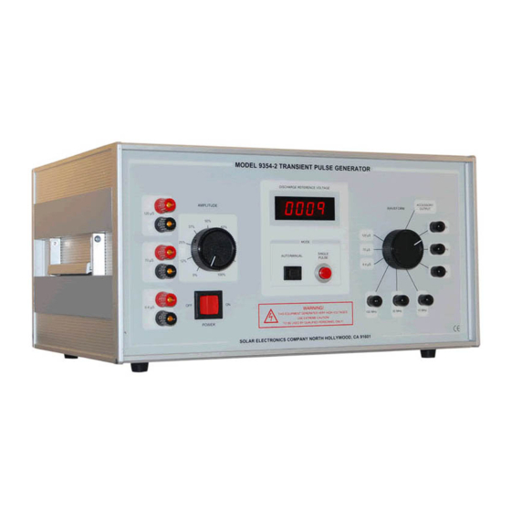
- Page 3 MODEL 9354-2 TRANSIENT GENERATOR DISCHARGE VOLTAGE 3200.00 AMPLITUDE WAVEFORM 120 uS 120 uS 10 kHz 70 uS 100 kHz AUTO/MANUAL TRIGGER 70 uS 100% 6.4 uS MODE 1MHz 100 MHz 30 MHz 10 MHz POWER 6.4 uS SOLAR ELECTRONICS HOLLYWOOD CALIF. 90038 FEATURES ■...
-
Page 4: Table Of Contents
SOLAR MODEL 9354-2 Table of Contents OPTIONAL ACCESSORIES ............. 1 Type 6220-4 High Voltage Transformer............1 Type 9335-2 Universal Coupling Device............1 Type 9410-1 High Voltage Attenuator............1 Type 9454-1 High Voltage Attenuator............1 Type 9142-1N Injection probe ..............1 Type 9616-2 High Voltage Surge 70 uS. -
Page 5: Optional Accessories
50 ohm input impedance) ■ Type 9142-1N Injection probe . For injecting 1MHz to 100 MHz damped sine wave ■ Type 9616-2 High Voltage Surge 70 μS. Solar Electronics Company... -
Page 6: Description
30 MHz, and 100 MHz) and three double exponential pulses (6.4 μS, 70 μS, 120 μS). Modes of Operation - The Model 9354-2 has three modes of operation. A front panel switch selects either AUTO / MANUAL single pulse. The waveform selector switch also... -
Page 7: High Energy Outputs
EXTERNAL impedance network is used (see application NOTES) CAUTION! TURN SELECTOR SWITCH TO 120uS POSITION than turn AMPLITUDE KNOB TO ZERO, AND PULSE THE 120 uS TO DISCHARGE ALL CAPACITORS. Solar Electronics Company... -
Page 8: Specifications (All Verification Testing Should Be Done At 50% To Prolong Life)
Power Line Fuses ....115 V unit: 2 @ 3A Slow-Blow, or 230 V unit: 2 @ 1.5A Slow-Blow PHYSICAL CHARACTERISTICS Net Weight ........................55 Lbs. (25 Kg) Shipping Weight ......................58 Lbs. (26.3 Kg) Height ........................9.12 In. (222 mm) Width ........................17.12 In. (435 mm) Depth ........................13.50 In. (343 mm) Solar Electronics Company... -
Page 9: Application
3200 volts peak to meet the requirements of DO-160D, Section 22, Table 22-2,. Double exponential: The double exponential pulses were specifically designed to meet the requirements of DO-160C, Section 22, (See table below). Solar Electronics Company... -
Page 10: Application Do 160E Section 22
Vp= Peak open circuit Voltage (V) Ip= Peak test limit Current (A) 5.2 Calibration Setup (100 ohm loop) Equipment used Solar Model 9354-2 Transient Pulse Generator. Type 9357-1 Calibration Fixture. Type 9335-2 Multiple Coupling Injection Probe. Type 9841-1 High voltage 50 ohm termination. -
Page 11: 5.3 Open Circuit Voltage
87 % IMPORTANT NOTE LIMITATIONS of newer Digital Oscilloscope: DIGITAL Oscilloscopes that have a maximum 1 volt per division with a 50 ohm input cannot view the 3200 volt open circuit damped sinusoidal, or the 1600 Solar Electronics Company... -
Page 12: Waveform 5A
Category L & M is intended for equipment and interconnect wiring that will be installed in severe electromagnetic environments. Such levels might be found in all-composite aircraft or other exposed area in metallic aircraft. Category X No test required. Solar Electronics Company... -
Page 13: Operation
R.M.S. flowing through them. NOTE: Turning off the Model 9354-2 power switch will slowly discharges the main pulse storage capacitors. Pulsing in the 120 μS long wave possession will discharge the capacitors (faster). Type 9335-2 Multi-port Coupling Device Connections - Connect the coaxial cable to... - Page 14 70 μS double exponential discharge. The junction between R35 and R36 is connected to the positive terminal of the modules front panel jacks to provide the 70 μS pulse duration when loaded with 2 ohms. Solar Electronics Company...
-
Page 15: Application Notes
22 ohm and 5.6 ohm is 340 volts and the peak circuit current is 68 amps. This results in a output impedance of 5 ohms. Solar Electronics Company... -
Page 16: 10. Swr & Discharge Voltage
10. SWR & Discharge voltage: The Model 9354-2 Displayed discharge voltage is in reference to the open circuit discharge voltage. This will coincide with an open circuit voltage onto a SOLAR 9454-1 Attenuator, 600 ohm input to 50 ohm output, with a calibrated attenuation of 40 dB. - Page 17 0.1 Ω resistor was connected in series with the calibration loop and the voltage waveform measured across the resistor using a calibrated scope. The waveform was plotted and the peak current SOLAR ELECTRONICS COMPANY...
- Page 18 In an effort to use existing equipment, the second proposed solution was selected. This was accomplished by connecting the 70 μS output of the Model 9354-2 Transient Pulse Generator into the primary of a Type 6220-4 Audio Isolation Transformer (2:1 step down) and connecting the secondary into Port 2 of the Type 9335-2 Multi-port Coupling Device (2:1 step down).
- Page 19 The configuration of each test setup is diagramed and the equipment involved is identified or described in Configuration 1 through 3, and the plotted short circuit current waveforms are shown in Figures 1 through 5. Test Configuration 1 Standard setup Test Configuration 2 Use of Type 6220-4 SOLAR ELECTRONICS COMPANY...
- Page 20 Figure 5, Short Circuit Current Waveform, Test Configuration 2. 70 μS into two Type 6220-4 into the 4:1 port of the Type 9616-1 injection probes. Measuring the short circuit current across a Non-inductive .1 ohm resistor. 800 A. SOLAR ELECTRONICS COMPANY...
- Page 21 Conclusions: If the full capabilities of the Model 9354-2 Transient Pulse Generator or other pulse generators that have selectable waveforms, different source and load impedances, and various voltage and current outputs are to be realized; then either several differently designed and sized coupling devices, or a single larger sized coupling device designed with several selectable configurations would be required.
- Page 22 The generator source impedance is checked by installing a 1 ohm resistor across the output of the generator and verifying that the voltage drops to half the open circuit voltage +/- 10%. Open circuit voltage Generator source impedance verification SOLAR ELECTRONICS COMPANY...
- Page 23 Short the secondary of the 6220-2 audio isolation transformer. Using the Solar type 7541-1 spike receptor probe (20 dB correction factor) and a 9410-1 high voltage attenuator (40 dB correction factor), measure the waveform and verify it meets the requirement for time to crest and duration. Calibration loop short SOLAR ELECTRONICS COMPANY...
- Page 24 SOLAR ELECTRONICS COMPANY...
- Page 25 SOLAR ELECTRONICS COMPANY...
- Page 26 SOLAR ELECTRONICS COMPANY...
- Page 27 SOLAR ELECTRONICS COMPANY...
Need help?
Do you have a question about the 9354-2 and is the answer not in the manual?
Questions and answers