Table of Contents
Advertisement
Quick Links
Provided by:
Rentals • Sales • Calibration • Service
Advanced Test
®
Equipment Corp.
INSTRUCTION MANUAL
FOR
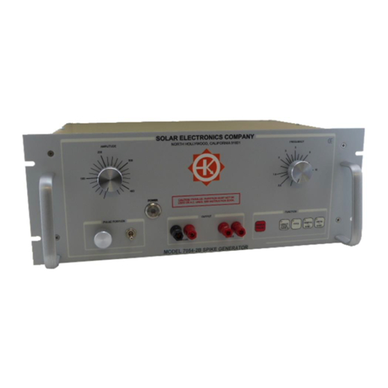
MODEL 7054-2B
SPIKE GENERATOR
Rev. 1.0 October 16, 2017
Rev. 1.1 August 20, 2019
Rev.1.2
Solar Electronics Company
A Division of A.T. Parker, Inc
10866 Chandler Boulevard
North Hollywood, California 91601
Telephone: (818) 755-1700 Fax: (818) 755-0078
www.solar-emc.com
www.atecorp.com
(800) 404-ATEC
July 15, 2020
.
Advertisement
Table of Contents

Related Manuals for Solar Electronics 7054-2B


Summary of Contents for Solar Electronics 7054-2B
- Page 1 ® Provided by: Equipment Corp. (800) 404-ATEC Rentals • Sales • Calibration • Service INSTRUCTION MANUAL MODEL 7054-2B SPIKE GENERATOR Rev. 1.0 October 16, 2017 Rev. 1.1 August 20, 2019 Rev.1.2 July 15, 2020 Solar Electronics Company A Division of A.T. Parker, Inc...
-
Page 2: Table Of Contents
TABLE OF CONTENTS 1.0 Application…………………………………………………………………………... 2.0 Description……………………………………………………………………..…..3.0 Specifications………………………………………………………………………. 4.0 Operation…………………………………………………………………………..4.1 General…………………………………………………………………..4.2 Interconnections for Parallel Injection…………………………... 4.3 Interconnections for Series Injection…………………………..... 4.4 Function Select Buttons……………..…………..………...………… 4.5 Single Pulse Operation..…………………..…………………………. 4.6 Auto Repetition Rate………………..…..…………………………..4.7 Pulse Positioning …………………………..………………………… 4.8 Spike Amplitude ……………………..…………………………..4.9 Amplitude with Low Impedance Loads ………………………..... - Page 3 Diagram 1 – Parallel Injection on DC Line……………………………………………….………..7 Diagram 2 – Series Injection on AC Line……………………………….…………………………8 Diagram 3 – Series Injection on DC Line, Measuring 7054-2B Spike Only…….………..8 Diagram 4 – Setup for Pulse Position Test on 400 Hz Line………………….……………….10 Images Image 1 –...
-
Page 4: Application
RFI/EMI specifications. 2.0 Description The Model 7054-2B spike generator provides a transient pulse (spike) with amplitude adjustable up to 400 V peak into 5 Ω load. Using series injection into a resistive load, the output transient closely follows an idealized curve with less than 10 µS rise time and the Waveshape falling to zero in approximately 120 µS. -
Page 5: Specifications
3.0 Specifications Spike Repetition Rate Continuously adjustable from 0.8 PPS to 10 PPS Spike Amplitude Continuously adjustable from 10 V to 400 V peak Spike Duration Output falls to 50% of full voltage in approximately 42 µS and to zero in approximately 120 µS with a 5 Ω... -
Page 6: Operation
4.0 Operation 4.1 General Parallel Injection is to be only used for DC lines. Series Injection is most often used on AC lines. CAUTION! PARALLEL INJECTION MUST NOT BE USED ON AC LINES SINCE SEVERE DAMAGE TO THE SPIKE GENERATOR WILL RESULT. SERIES INJECTION CAN BE USED ON EITHER AC OR DC LINES. -
Page 7: Interconnections For Parallel Injection
Electronics Company Isolation Transformer* or equivalent at the power input to the oscilloscope. All output terminals on the Model 7054-2B are isolated from the case of the unit. When parallel injecting the spike into a DC line, it is desirable to use an inductor in series with the power source so that the spike is applied to the test sample without the RF shunting effect of the power source impedance. -
Page 8: Interconnections For Series Injection
See Diagram 3. Precautions must be taken to avoid grounding the hot side of the power line through the case of the oscilloscope. DIAGRAM 3 - SERIES INJECTION ON DC LINE OSCILLOSCOPE MEASURING 7054-2B SPIKE ONLY Solar Model 7054-2B... -
Page 9: Function Select Buttons
50/60 Hz line. See Diagram 4. This is accomplished by removing the parallel blade connector, P1, from its socket (adjacent to the fuses on the rear panel) and connecting it to a primary AC line voltage source equivalent the 7054-2B’s normal power source. -
Page 10: Diagram 4 - Setup For Pulse Position Test On 400 Hz Line
DIAGRAM 4 - SETUP FOR PULSE POSITION TEST ON 400 Hz LINE Solar Model 115 -230V 7054-2B Solar Oscilloscope 400 Hz Isolation Transformer* Line Parallel Series AC line input Test Sample Line Series Solar Type 7032-1 for 115 V Solar Type... -
Page 11: Spike Amplitude
4.9 Amplitude with Low Impedance Loads Since the internal impedance of the Model 7054-2B spike generator is of the order of 0.5 Ω, the amplitude into a matched load will be one half that of the open circuit amplitude. This characteristic enables the operator to estimate the load impedance when it is approaching the internal impedance of the generator, Solar Model 7054-2B. -
Page 12: Pulse Shape
4.10 Pulse Shape When unloaded or connected to a purely resistive 5 Ω load, the spike shape is approximately that of Graph 1. Graph 1 – Pulse shape with 5 Ω load on Either Series or Parallel Output Vertical: 60 V/div Horizontal: 20 µS/div Frequency:... -
Page 13: Calibration Assistance
60 Hz AC of the Model 7054-2B generator’s default voltage. 5.2 Preliminary Procedure Plug the AC line voltage source into the back-panel AC receptacle of the Model 7054-2B. Connect the 5Ω 6W (Solar Type 8525-1) resistor across the SERIES output terminals on the Model 7054-2B. -
Page 14: Check And Adjustment Of Auto Pulse Frequency
PCB, inside the Model 7054-2B. To access the main PCB, be sure the line cord of the Model 7054-2B is disconnected from the primary power source. Remove screws from the bottom cover and detach the bottom cover to expose the main PCB. -
Page 15: Check And Adjustment Of Range For Pulse Position At 400 Hz
To check and adjust the range of the PULSE POSITION control at 400 Hz, proceed as follows: Disconnect blower from the AC receptacle on the back of the Model 7054-2B. Connect the male plug of the fan to the secondary AC line voltage source providing 50Hz or 60Hz AC of the Model 7054-2B generator’s default voltage.
Need help?
Do you have a question about the 7054-2B and is the answer not in the manual?
Questions and answers