
Related Manuals for HESCH HIMOD HE 5820 DI


Summary of Contents for HESCH HIMOD HE 5820 DI
- Page 1 HE 5820 DI ® HIMOD Function Module Operation manual (English) # 38101017 | 12.12.2014...
- Page 2 HESCH Industrie Elektronik GmbH, Documentation Department Copyrights © Copyright 2014 HESCH Industrie-Elektronik GmbH. All rights reserved. The content of this operating manual incl. images and design are subject to the protect of copyright and other laws regarding the protection of intellectual property.
-
Page 3: Table Of Contents
Table of Contents General ......................4 Features ......................4 HIMOD System ....................5 Safety Instructions ..................6 Maintenance, Repair, Converting ..............7 Cleaning ......................7 Assembly ...................... 8 ... -
Page 4: General
General General The digital input module HE5820 provides HIMOD systems with eight digital inputs. The module communicates with the field bus coupler over an asynchronous serial RS485 connection (T-Bus). The module can be pulled out or plugged in during operation (Hot Swap). The module supplies a sensor supply per input of 24 V DC with a maximum current of 25 mA for the direct connection of e.g. -
Page 5: Himod System
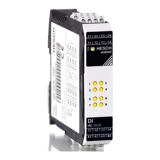
General HIMOD System Fig. 1 HIMOD – Module Image HIMOD is an intelligent I/O system for all common field bus standards. Every function module provides the field bus coupler with process values. Through the integrated module processor the field bus coupler is relieved of measured value calculations. -
Page 6: Safety Instructions
Safety Instructions Safety Instructions This device has been constructed and tested in accordance with VDE 0411-1 / EN 61010-1 and left our works in perfect safety-related condition. The device is in complete conformity with the European Directive 89/336/EEC (EMC) and is provided with the CE marking. The device was tested before shipment and has passed the tests prescribed in the test plan. -
Page 7: Maintenance, Repair, Converting
Safety Instructions TAKING OUT OF OPERATION If the device is to be taken out of operation, then the auxiliary energy is to be disconnected at all poles. The device is to be secured against unintentional operation. If the device is connected together with other devices and / or equipment, then the consequences are to be considered and appropriate precautions are to be taken before switching off. -
Page 8: Assembly
Assembly Assembly 99.0 22.5 Fig. 2 Dimensions click Fig. 3 Assembly / Disassembly The device is intended for vertical assembly on 35 mm top-hat rails according to EN 50022. Devices of the HIMOD – family can be mounted directly next to each other. -
Page 9: Plug Connectors
Assembly The place of installation should be as free of vibrations, aggressive media (such as acids, caustic solutions), liquids, dust or other suspended matter as possible. The module contains no parts subject to maintenance and does not need to be opened by the customer. The device may only be used in environments with the approved level of protection. -
Page 10: Front View And Indications
Assembly Front View and Indications LED ok/err On green Module OK Flashing green Configuration error Flashing red No voltage supply of the outputs Voltage supply interrupted LED 1 – 8 yellow Input ’ON’* Input ’OFF’* * with 'logical' 'ON'. If the inputs have been inverted, the inputs are not actively connected. -
Page 11: Electrical Connection
Electrical Connection Electrical Connection Connection Diagram The 4-pole device plug connectors are used for the module function. Input Input 24VDC out max. 200mA Input Input Version PNP, NPN Version POT-free Fig. 6 Front View and Connector Pin Assignment A faulty connection can lead to the destruction of the device! ®... -
Page 12: Connection Specification
Electrical Connection Connection Specification The HE 5820 module exists with various internal circuits. 4.2.1 HE 5820 PNP Art. No.: HE58200000 Version PNP HE 5820 +24V +24V 200mA 200mA 4.2.2 HE 5820 NPN Art. No.: HE58201000 Version NPN HE 5820 +24V +24V +24V +24V... -
Page 13: Functional Description
Functional Description Functional Description The HE 5820 module provides the HIMOD bus coupler with eight inputs. The functions of the module are parameterised in the device with the software tool 'SmartControl'. Fig. 9 Screenshot Parameterisation of Module Functions Module Functions Parameterisation Table Abbr. -
Page 14: Meaning Of The Module Status Information
Functional Description Meaning of the Module Status Information The module status is depicted in the status byte. Every bit represents one item of information. The meaning of the individual bits is to be taken from the table. Meaning Remark Bit is not used Is taken from the module Bit is not used... -
Page 15: Smartcontrol - Engineering Tool
SmartControl – Engineering Tool SmartControl – Engineering Tool The engineering tool 'SmartTool' parameterises the function modules of an HIMOD device and configures the system of the device. The physical connection is established from a PC with RS232 port and a special cord to the front port ’SmartPort’... -
Page 16: Technical Data
Technical Data Technical Data Module Function Module type: Input module for HIMOD systems 8 x 24 V DC in 2 switching groups Version: Design as PNP, NPN or potential-free version direct connection of 3-wire sensors input specification according to IEC 1131 Sensor supply: Per channel there is a sensor supply of 24 V DC (±10 %) available with a maximum current of 25 mA. -
Page 17: Assembly And Connection
Technical Data Immission: DIN EN 61000-6-2 Type of protection: Casing front: IP 20 Casing: IP 20 Connections: IP 20 Assembly and Connection Assembly: on 35 mm top-hat rails according to EN 50022 locking with metal foot bar position for use: vertical Casing: material: polyamide PA 6.6 flammability class: V0 (UL 94)
Need help?
Do you have a question about the HIMOD HE 5820 DI and is the answer not in the manual?
Questions and answers