
Subscribe to Our Youtube Channel
Related Manuals for HESCH HE 5712 Compact


Summary of Contents for HESCH HE 5712 Compact
- Page 1 HE 5712 Compact / Modular Solenoid valve control Operating Instructions (Original German version) 372048 | Version 1.4...
- Page 2 Editor: HESCH Industrie Elektronik GmbH, Documentation Department Copyrights © Copyright 2020 HESCH Industrie-Elektronik GmbH. All rights reserved. The content including pictures and the design of these operating instructions are subject to copyright protection and other laws for the protection of intellectual property. The distribution or modification of the contents of this manual is not permitted.
-
Page 3: Table Of Contents
ASIC AFETY NSTRUCTIONS ....................7 AFETY IN THE INDIVIDUAL OPERATING PHASES DEVICE DESCRIPTION ..........................9 ..............................9 VERVIEW 3.1.1 HE 5712 Compact ..........................9 3.1.2 HE 5712 Modular........................... 10 ......................12 ISPLAY AND PERATING LEMENTS ........................13 IFFERENTIAL PRESSURE COLUMN ............................ - Page 4 Document History Version Date Description 2018-06-14 First draft (Translation) 2018-12-18 Chapter 6.7: Pictures for PARA and ENTER key corrected 2019-08-08 Chapter Electrical Commissioning: Note added for entering password prior to commissioning. Chapter 5.3 and 7.1: „12,14,16“ added for mass in the note. 2020-01-07 Position of the note in 7.1.
-
Page 5: Legal Provisions
Legal provisions Manufacturer HESCH Industrie-Elektronik GmbH, Boschstraße 8, D-31535 Neustadt, Germany Intended Use The solenoid valve control HE 5712 is used for cleaning industrial filter systems. The controller can be operated within the operating and environmental conditions approved in this manual without impairing its safety. -
Page 6: Safety Information
Safety Information Symbols and Basic Safety Instructions This chapter contains important safety regulations and notes. To protect against personal injury and material damage, it is necessary to read this chapter carefully before working with the device. Symbols used The following symbols are used in this manual. All safety instructions have a uniform structure. Personal Injury Warning! The severity of the danger is indicated by the respective signal word. -
Page 7: Safety In The Individual Operating Phases
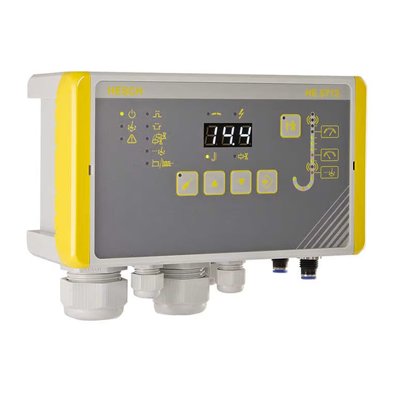
Observe the safety measures according to BS EN 61340-51/-3 to avoid electrostatic discharge! Explosion Prevention! The HE 5712 Compact (Fig. 1) is suitable for use in explosion zone 22. Before opening the device, it is essential to ensure that no explosive environmental conditions, such as dust generation, exist HE 5712 Operating Instructions # 372048 | Version 1.4... - Page 8 Machine Identification The HE 5712 Compact (Fig. 1) is marked with: II3D Device category Use in Zone 22 for dust during normal operation Designates an electrical equipment Type of ignition protection: Protection by housing IIIC Dust group: Conductive dusts T135°C...
-
Page 9: Device Description
Device Description The solenoid valve control HE 5712 is available in different versions. Overview 3.1.1 HE 5712 Compact HE 5712 (Compact) HE 5712 (Compact) Connection area HE 5712 Operating Instructions # 372048 | Version 1.4... -
Page 10: He 5712 Modular
3.1.2 HE 5712 Modular HE 5712 (Modular) Operating Unit Rear panel HE 5712 (modular) Operating Unit HE 5712 Operating Instructions # 372048 | Version 1.4... - Page 11 HE 5712 (Modular) control unit in standard rail enclosure (100 - 240 V AC) HE 5712 Operating Instructions # 372048 | Version 1.4...
-
Page 12: Display And Operating Elements
Display and Operating Elements Display and Operating Elements Symbols Meaning Operating message Cleansing active Alarm active Pulse time Break time The number of valves is shown in the display and can be changed Post-cleaning cycles are shown in the display and can be changed Total / partial cycle is shown in the display and can be changed Interruption due to defective valve line or solenoid valves Short circuit of a valve line (overcurrent) -
Page 13: Differential Pressure Column
Symbols Meaning PARA key: parameterisation mode On/Off UP key: increase the displayed value DOWN key: decrease the displayed value ENTER key: Confirm the displayed value TEST key: Test mode On/Off Display Normal operation: current differential pressure, current valve Parameterisation mode: parameter values and alarm notes ... -
Page 14: Technical Data
Technical Data Technical Data 0…35 mbar Measuring range (please refer to 0…90 mbar the nameplate) 0…450 mbar Measuring range 0…35 mbar: 160 mbar Max. differential pressure: Measuring range 0…90 mbar: 400 mbar Measuring range 0…450 mbar: 2000 mbar Medium Air and dry, non-aggressive gases Basic accuracy: ±... - Page 15 Ambient conditions Climate -20° – +70°C Storage -40° – +85°C Transport Operation Compact housing -20°C – +50°C in EX Zone 22: -20° – +40°C Modular -20°C – +50°C No EX approval Relative humidity Relative humidity 95%, no condensation allowed, KUF according to DIN 40400 Subject to technical changes.
-
Page 16: Mounting
The special regulations must be observed, see chapter 2.2 Safety in the individual operating phases on 7. Dimensions 4.1.1 HE 5712 Compact Dimensions of compact housing HE 5712 Operating Instructions # 372048 | Version 1.4... -
Page 17: He 5712 Modular Operating Unit (Panel Mounting Housing)
Drilling jig (only for the operating unit - HE 5712 Modular) Note! Upon receipt, check the delivery for completeness and visible defects. In the event of a complaint, contact your responsible HESCH representative immediately. HE 5712 Operating Instructions # 372048 | Version 1.4... -
Page 18: Electrical Commissioning
Electrical Commissioning Before switching on the device, observe the following points: Connect the cable firmly to the glands. The power supply must correspond to the voltage indicated on the nameplate. The device may only be operated in closed condition. ... -
Page 19: Read Out And Set Password
100 - 240 V AC and device versions only with 24 V DC mains voltage. 5.3.1 Compact Housing Open the housing on the right hinge lock using a slotted screwdriver: (Figur 10): Opening the housing of the HE 5712 Compact HE 5712 Operating Instructions # 372048 | Version 1.4... -
Page 20: Housing For Panel Mounting
HE 5712 Compact with 24 V DC supply voltage 5.3.2 Housing for Panel Mounting The supply voltage is applied centrally to the control unit . The operating unit gets its 24 V DC supply via a patch cable (CAT5 or better) from the control unit . -
Page 21: Valve Connections
The control automatically extends the effective pause time to the above ratio. The software version can be determined by a serial number query on the page www.hesch.de/support/seriennummern.html Note! All valve outputs of a system refer to the same mass (-) (12, 14, 16). It is permitted to use one ground line for several inputs. -
Page 22: Parameterisation
Parameterisation Parameterisation with Device Keyboard Press the PARA key to change the values of the system parameters. A flashing LED indicates the value currently to be changed. If a password has been assigned, cod is displayed. Press the ENTER key. Press the UP and DOWN keys to enter the password digit by digit. -
Page 23: Parameter Table
Parameter Table Parameters Adjustment range Default Pre-assignment setting 0 … 999 Password 3-digit number that must be entered before parameters can be changed. 0 = no password protection 0.01 … 9.99 s Pulse time 0.10 s 0.10 s 0.1 … 999 s Break time 5.0 s 5.0 s... - Page 24 Parameters Adjustment range Default Pre-assignment setting Post-cleaning Threshold OFF, 2.0 mbar 2.0 mbar 0.0 … 500.0 mbar [mbar] (at 0...35 mbar measuring range) The threshold is activated when the lower threshold is exceeded. 5.0 mbar If the threshold is (at 0...90 mbar activated and the measuring range)
- Page 25 The following parameters can only be changed with the "EasyTool Controls" program (see also chapter 6.4 Parameterisation with Service PC) Parameters Adjustment Default Pre- range setting assignment 0.1 … 10.0 s p-Filter 2.0 s p-Filter constant for damping the p measurement. 1 …...
-
Page 26: Offset For Zeroing
When parameterising several devices, parameterisation with a service PC is recommended. The USB / TTL adapter required for this is available from HESCH. The parameters can be changed via PC and the "EasyTool Controls" program. The program can be used to save a configuration or to restore a saved configuration. -
Page 27: Reset Default Settings
Reset Default Settings Note! If a password has been assigned, it must be entered during reset. After the reset, the password is 0. A new password must be assigned. (see chapter 5.2 Read out and set password). Switch on the device while keeping both keys UP and DOWN pressed for 5 seconds. -
Page 28: Operation Of The Control
Operation of the Control Normal Operation Operation is started by applying the supply voltage. The valve cleaning is controlled via the inputs and outputs of the device. Current output Note! All valve outputs of a system refer to the same mass (-) (12, 14, 16). It is permitted to use one ground line for several inputs. -
Page 29: Test Function
Test Function Press the TEST key to perform a function test of the valves. Select the desired valve with the UP / DOWN keys. Press ENTER (The selected valve is permanently operated with the stored pulse and pause time). If necessary, test the next valve. If the TEST key is pressed for more than 2 seconds, a test cycle is performed on all released valves. -
Page 30: Differential-Pressure Measurement
Differential-pressure measurement (raw gas) (Pure gas) Differential Pressure Measurement Connections (HE 5712 Compact) (raw gas) (Pure gas) Pressure connections on the control unit (HE 5712 Modular) The differential pressure is measured internally and transmitted as 4... 20 mA signal to the higher-level controller or to an indicating device. - Page 31 Differential Pressure Measuring range of the sensor High alarm Precoating Upper threshold Start Cleansing Lower threshold Delay time Stop cleansing 5 min Low alarm Start Post-cleaning Time Post- Cleansing cleaning Cleansing Alarm relay Time course of the differential pressure measurement HE 5712 Operating Instructions # 372048 | Version 1.4...
-
Page 32: Error Messages
Error Messages Display Cause Troubleshooting The differential The differential pressure signal is Check differential pressure display below the permissible measuring pressure shows range Check external screw “_ _ _“ connection The differential The differential pressure signal is Check differential pressure display above the permissible measuring... -
Page 33: Maintenance And Service
Disposal Dispatch metals and plastics for recycling. Electrical and electronic components must be collected separately and disposed of accordingly. Dispose of assembled printed circuit boards professionally. Service HESCH Industrie-Elektronik GmbH Boschstrasse 8 D-31535 Neustadt Telefon: + 49 5032 9535-90 www.hesch.de info@hesch.de...
Need help?
Do you have a question about the HE 5712 Compact and is the answer not in the manual?
Questions and answers