
Related Manuals for schmersal bp408


Summary of Contents for schmersal bp408
- Page 1 Operating Instructions The bp408 Safety Circuit General instructions EC Type Examination Safety Circuit...
- Page 3 The common names, trade names, product identifications etc. in this document may also be registered brands even if they are not specifically identified and as such are subject to statutory provisions. Böhnke + Partner GmbH, BlueModus, WinMOS®300, CANwizard®, Lift2CLOUD® Operating Instructions- The bp408 Safety Circuit - Contents...
-
Page 4: Table Of Contents
Functional description of safety circuit ..............22 4.4.2 Error analysis of safety circuit ................... 22 4.4.3 Testing ........................23 Connection of SPL-01 ....................24 Safety circuit status bar on display ................ 24 Tecnical Data ......................25 Operating Instructions- The bp408 Safety Circuit - Contents... -
Page 5: General Information
To improve clarity and structuring, the manual was divided into multiple parts. The Operation Instructions of the bp408 Safety Circuit" also considers the dangers and risks, which may lead to severe health related as well as economic damage in case of misuse. -
Page 6: Intended Use
This symbol is used when inaccurate compliance with or failure to comply with instructions or procedures can result in injuries or fatal accidents due to electric current. NOTE! This symbol is used to bring attention to a specific characteristic. Operating Instructions- The bp408 Safety Circuit - General Information... -
Page 7: Product Certificates
Document area in online catalogue for the bp408 EU Type Examination The system module bp408 contains an electronic monitoring unit for the safety circuit and a precontrol for the contactors. Moreover, a safety circuit (SMZ) is located on the circuit board. The safety circuit can be used in the following cases of DIN EN 81-20/-50 and DIN EN 81-1/-2: ... -
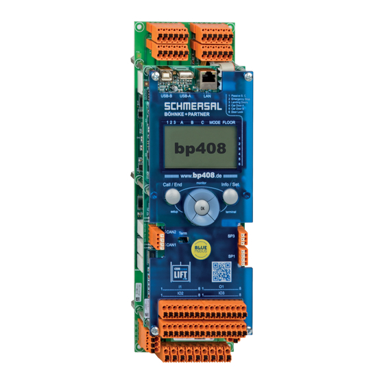
Page 8: Eu Type-Examination Certificate Spl-01 With Smz
EU Type-Examination Certificate SPL-01 with SMZ Figure 1: System module bp408 - Subarea of the printed circuit board SPL-01 Reg. no. 01/208/4A/6135.00/18 dated 2018-07-26. Operating Instructions- The bp408 Safety Circuit - Product Certificates... -
Page 9: Ucm Requirements
1.0 m between the cabin floor and the upper edge of the shaft access. The apron fitted beneath the cabin may only allow for a gap of max. 200 mm. Fig. 2 Operating Instructions- The bp408 Safety Circuit - UCM requirements... -
Page 10: Observation Of The Situation
This block is also active after a power failure and restoration of power and can only be reset from directly within the control system. The error is also entered into a fault stack memory including its date and time. Operating Instructions- The bp408 Safety Circuit - UCM requirements... -
Page 11: General Information On Ucm Function
RCD circuit breaker culminating in non-triggering. The maximum permissible release current of these selective RCD circuit breakers that are sensitive to universal current must not exceed value I =0.3 A. ΔN Operating Instructions- The bp408 Safety Circuit - UCM requirements... -
Page 12: Notes On Installation
If the braking system cannot bring the cabin to a stop within the required UCM distances, then the door zone may be reduced in size. The maximum acceleration for relevelling must be considered. h) The lift controller monitors the level position of the cabin. Operating Instructions- The bp408 Safety Circuit - UCM requirements... -
Page 13: Notes On Test
The specialist must follow the described instructions step by step. e) A testing program is integrated with the bp408 system module for support purposes. f) The specialists check the provided acceptable limit values of EN 81-20/50 and/or EN 81-1/2+A3 (for example distances) on the elevator system by measuring. -
Page 14: Bp408 Testing Program
During the test the overspeed monitoring of the lift controller is disabled. 3.3.1.1 Step 1 In order to check this function prior to commissioning, the bp408 system module contains a test program The test program is activated by a password in the maintenance menu. - Page 15 To manually open the safety circuit, the control system may contain a switch designated "UCM Test I – 0" (2S300) if ordered by the customer. Operating Instructions- The bp408 Safety Circuit - UCM requirements...
-
Page 16: Step 2
A corresponding description pertaining to each inverter is provided on request. Here, the brake and trip contactors are actuated with the door opened and the safety circuit activated until the safety circuit triggers and terminates the process. Operating Instructions- The bp408 Safety Circuit - UCM requirements... -
Page 17: Step 3
A braking system tested in accordance with UCM engages and brings the cabin to a stop. The traveled distance is shown on the display: After the test, the traveled distance can be read off using the display. Operating Instructions- The bp408 Safety Circuit - UCM requirements... -
Page 18: Extra Requirements For Ucm Testing Of Traction Elevators With Gears
(GB) keeps the arresting pendulum in the trigger position. The cam wheel is blocked, and the governor rope immediately engages the " safety gear". The power supply Operating Instructions- The bp408 Safety Circuit - UCM requirements... -
Page 19: Extra Requirements For Ucm Testing Of Hydraulic Elevators
"UCM test (A3) terminated", so that both processes are documented. The release of blocking conditions is documented in the message stack. In this regard, it is differentiated whether the block was lifted via terminal or menu. Operating Instructions- The bp408 Safety Circuit - UCM requirements... -
Page 20: Circuit Board Spl-01
12B, 13, 14 correspond to DIN EN 60664 and/or DIN EN 60950. The safety circuit with query unit on bp408 is secured up to a maximum of 2 A. The connection of neutral conductor, mains potential "NN", is made using terminal 9 of the bp408 module. -
Page 21: Testing Of Wiring For Query Circuit
7. Then connect the wire to terminal 14 again. 8. If the trip contactors disengaged during every testing process, the wiring was made correctly, and no changes must be implemented. 9. The elevator is now operational again. Operating Instructions- The bp408 Safety Circuit - Circuit Board SPL-01... -
Page 22: Safety Circuit On Spl-01
This means that the unlocking zone can only be approached with the door closed and the door lock switch engaged. When using the safety circuit as a substitute for Operating Instructions- The bp408 Safety Circuit - Circuit Board SPL-01... -
Page 23: Testing
2. Disconnect the wire on connection ZS, which causes the encoder element to no longer be active as the signal encoder (channel 1). 3. The release signal is internally activated by the bp408 system module and relay K552 engages. 4. If the zone is reached, relay K553 engages, but relay K554 cannot engage due to the circuit. -
Page 24: Connection Of Spl-01
The safety circuit status bar is displayed in all menus following information: Pos. Meaning Terminal Passive Safety Circuit Emergency Stop Shaft Door Car Door A Car Door B Door Lock Operating Instructions- The bp408 Safety Circuit - Circuit Board SPL-01... -
Page 25: Tecnical Data
4000 m at max. 48 VAC/VDC Atmosphere: no corrosive gases no conductive dusts no ionizing radiation Measures (H x B x T): 315 mm x 100 mm x 80 mm Operating Instructions- The bp408 Safety Circuit - Technical Data...