Cateye Enduro 2 CC-ED200N - Cyclocomputer Manual
- Limited warranty (4 pages) ,
- User manual
Advertisement
- 1 Precautions
- 2 SETTING UP
- 3 Installation
- 4 Setting Up the Computer
-
5
OPERATING THE COMPUTER
- 5.1 Changing the Data Displayed
- 5.2 Starting/Stopping the Recording
- 5.3 Auto Mode (Automatic Recording)
- 5.4 Moving TIME, AVERAGE SPEED and MAX SPEED to Upper Display
- 5.5 Resetting the DISTANCE 1, TIME, MAX SPEED and AVERAGE SPEED Functions
- 5.6 Wheel Setting A and B and Changing the Wheel Setting
- 5.7 Power Saving Function
- 6 Maintenance
- 7 Trouble-Shooting
- 8 Replacing the Battery
- 9 ALL CLEAR OPERATION
- 10 Manually Replacing Mileage (Odo) into Odometer
- 11 Specifications
- 12 LIMITED WARRANTY
- 13 Documents / Resources
Precautions

- Do not concentrate too much on the computer operations while riding.
- Be sure to securely mount the magnet, sensor and bracket on your bicycle, and periodically check to insure they are mounted securely.
- Used batteries must be disposed of properly and in accordance with all local regulations.
- Do not leave the main unit exposed to direct sunlight. Never disassemble the computer.
- To clean the computer, use mild soap and a soft cloth. Wipe dry with a soft cloth. Paint thinner, benzine, alcohol or other chemicals may damage the surface.
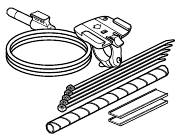
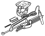
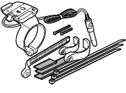
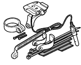
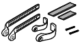
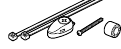
SETTING UP


- Bracket
- Wire
- Sensor
- Magnet
- Bracket Rubber Pad
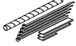
- Nylon Tie (5 pcs.)
- Spiral Tube
Installation

Attach the sensor and the magnet properly so that their positions meet the following conditions  and
and  .
.

- Align the magnet's
![]() center and the sensor's
center and the sensor's ![]() marking line while rotating the wheel.
marking line while rotating the wheel. - The clearance between the sensor
![]() and the magnet
and the magnet ![]() should be less than 5 mm.
should be less than 5 mm.
 center and the sensor's
  marking line while rotating the wheel.
 should be less than 5 mm.
- Sensor
Attach the sensor![]() temporarily, with the adhesive tape, to the inside of the right front fork.
temporarily, with the adhesive tape, to the inside of the right front fork.

- Magnet
Attach the magnet![]() to the right side spoke of the front wheel. Adjust the position of the sensor
to the right side spoke of the front wheel. Adjust the position of the sensor ![]() and the magnet
and the magnet ![]() so that it meets the conditions
so that it meets the conditions ![]() and
and ![]() in the "Important" column. Fix the sensor
in the "Important" column. Fix the sensor ![]() with the nylon ties
with the nylon ties

- Bracket
Secure the wire along the fork with the nylon ties![]() , and along the front brake cable with the spiral tube
, and along the front brake cable with the spiral tube ![]() . Apply the bracket rubber pad
. Apply the bracket rubber pad ![]() to the bracket
to the bracket ![]() , so that the band fits the handlebar. Fix it with the screw.
, so that the band fits the handlebar. Fix it with the screw.

Note: Allow enough wire clearance in the area marked with![]() to insure you can turn the handlebars all the way from side to side without pulling the wire.
to insure you can turn the handlebars all the way from side to side without pulling the wire. - Main Unit
Slide the main unit until it clicks into position. The contact is automatically connected. To re- move, slide it forward while pushing the lever.
Test
Install the main unit onto the bracket![]() . Spin the front wheel and see if the speed appears in the display. If not, re-adjust the position of the sensor
. Spin the front wheel and see if the speed appears in the display. If not, re-adjust the position of the sensor ![]() and the magnet
and the magnet ![]() so that it meets the conditions
so that it meets the conditions ![]() and
and ![]() in the "Important" column.
in the "Important" column.


 , and along the front brake cable with the spiral tube
  . Apply the bracket rubber pad
  to the bracket
  , so that the band fits the handlebar. Fix it with the screw.
 to insure you can turn the handlebars all the way from side to side without pulling the wire.
 . Spin the front wheel and see if the speed appears in the display. If not, re-adjust the position of the sensor
Setting Up the Computer

- Upper Display
(Usually Current Speed) - Mode Symbol
- Average Pace Arrow
- Speed Scale
- Auto Mode Symbol
- Wheel Selection Symbol
- Lower Display
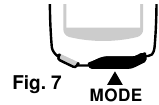
(Selected Function) - Mode Button
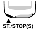
- S Button
- SET Button
- Battery Cover
- Contact
The speed sensor, handlebar bracket and wheel magnet should be installed first.
NOTE: To utilize previously accumulated Odometer data, refer to the section "Manually Replacing Mileage into Odometer" described in the last section of this manual.
The following set up is required before use:
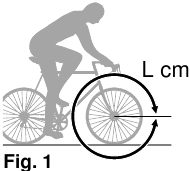
- Find the Wheel Calibration Number (Length of Tire Roll-Out)
Determine the length of the tire (Length in centimeters) from the Cross Reference Table. Alternately, you can find the most accurate wheel calibration number by rolling the tire on the ground. In this method, properly inflate the tires, sit on the bike and measure the distance of one wheel length. This distance in centimeters is the most accurate number. (Inches X 2.45 = Centimeters)
![]()
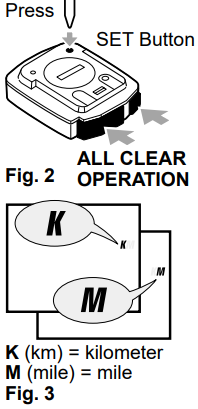
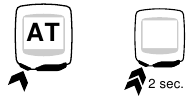
- Perform the ALL CLEAR OPERATION to clear the computer and set the speed scale:
Press the SET Button while pressing the MODE and START/STOP(S) Buttons (ALL CLEAR OPERATION: Fig. 2). The entire memory of the computer will be erased, and the complete screen will light up and then all fade away, leaving a flashing "K" on the screen. A press on the MODE Button will display "K" and "M" alternately (Fig. 3). Select your desired speed scale. Then press the START/STOP(S) Button to set the scale. The display moves to the next screen.
![]()
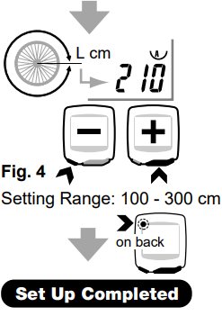
- Set the Wheel Circumference.
The number "210" (typical wheel circumference for 700x23C tires) will be displayed (Fig. 4).
Input the number from step 1 above.
Press the MODE Button to increase the number. Press the START/STOP(S) Button to decrease it. You can fast forward the numbers by holding either buttons down.
Set the number by pressing the SET Button.
Your computer is now set up for riding.
![]()
Cross Reference Table
| Tire size | L(cm) |
| 12 x1.75 | 94 |
| 14 x 1.50 | 102 |
| 14 x 1.75 | 106 |
| 16 x 1.50 | 119 |
| 16 x 1.75 | 120 |
| 18 x 1.50 | 134 |
| 18 x 1.75 | 135 |
| 20 x 1.75 | 152 |
| 20 x 1-3/8 | 162 |
| 22 x 1-3/8 | 177 |
| 22 x 1-1/2 | 179 |
| 24 x 1 | 175 |
| 24 x 3/4Tubular | 178 |
| 24 x 1-1/8 | 179 |
| 24 x 1-1/4 | 191 |
| 24 x 1.75 | 189 |
| 24 x 2.00 | 192 |
| 24 x 2.125 | 196 |
| 26 x 7/8 | 192 |
| 26 x 1(59) | 191 |
| 26 x 1(65) | 195 |
| 26 x 1.25 | 195 |
| 26 x 1-1/8 | 190 |
| 26 x 1-3/8 | 207 |
| 26 x 1-1/2 | 210 |
| 26 x 1.40 | 200 |
| 26 x 1.50 | 201 |
| 26 x 1.75 | 202 |
| 26 x 1.95 | 205 |
| 26 x 2.00 | 206 |
| 26 x 2.10 | 207 |
| 26 x 2.125 | 207 |
| 26 x 2.35 | 208 |
| 26 x 3.00 | 217 |
| 27 x 1 | 215 |
| 27 x 1-1/8 | 216 |
| 27 x 1-1/4 | 216 |
| 27 x 1-3/8 | 217 |
| 650 x 35A | 209 |
| 650 x 38A | 212 |
| 650 x 38B | 211 |
| 700 x 18C | 207 |
| 700 x 19C | 208 |
| 700 x 20C | 209 |
| 700 x 23C | 210 |
| 700 x 25C | 211 |
| 700 x 28C | 214 |
| 700 x 30C | 217 |
| 700 x 32C | 216 |
| 700C Tubular | 213 |
| 700 x 35C | 217 |
| 700 x 38C | 218 |
| 700 x 40C | 220 |
Setting the CLOCK
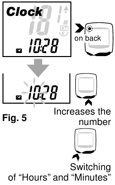
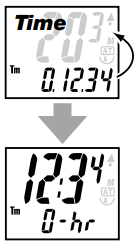
For setting the CLOCK, the TIME function must be turned off and the speed scale symbol (either M for Miles or K for Kilometers) must not be flashing (Fig. 5). The CLOCK is set to either 24- HOUR or 12-HOUR depending on the SPEED SCALE selected. In K (kilometers), a 24-HOUR CLOCK is selected, while in M (miles), a 12-HOUR CLOCK is selected.
- In the TIME Function(Tm), hold down the MODE Button, the
![]() mark will appear. This is an indication that you are in the CLOCK function.
mark will appear. This is an indication that you are in the CLOCK function. - Press the SET Button. The "HOURS" will flash. Use the MODE Button to change/advance the number, and the ST./STOP(S) Button to switch between "HOURS" and "MINUTES".
- Press the SET Button to set the CLOCK.
 mark will appear. This is an indication that you are in the CLOCK function.
OPERATING THE COMPUTER

Av
Average Speed
0.0-105 km/h
[0.0-65 mph]
Recording is possible up to 27 hours or 999.99 mile [km].
Changing the Data Displayed
Pressing the MODE Button changes the data displayed on the screen as shown in Fig. 6. A single press of the button will switch to the next main mode, and a holding down of the button for 2 seconds or longer will switch to the sub-mode. To get back to the main mode from the sub-mode, just press the MODE button.
Starting/Stopping the Recording
Pressing the ST./STOP(S) Button will start the recording of TIME, AVERAGE SPEED and DISTANCE 1 or 2, and a subsequent press will stop the recording. During the recording, the speed scale (K or M) will flicker.
Auto Mode (Automatic Recording)
You can set the computer to record TIME, AVERAGE SPEED and DIS- TANCE 1 or 2 automatically. This is called the AUTO MODE. The computer's sensor detects the motion of your wheel to start and stop recording automatically. (Once the AUTO MODE is set, you cannot start or stop the recording with the ST./STOP(S) Button.)
Activating AUTO MODE:
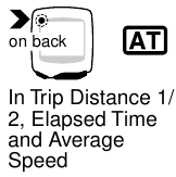
In the DISTANCE, TIME or AVERAGE SPEED function, press the SET button. The  symbol will appear on the screen to identify the AUTO MODE. You can take the computer out of the AUTO MODE in the same way.
Moving TIME, AVERAGE SPEED and MAX SPEED to Upper Display
You can move TIME, AVERAGE SPEED or MAX SPEED to the upper display, giving you larger font and an easy-to-see screen. When the computer is set in the AUTO MODE ( ), the switching is possible by displaying the mode you would like and pressing the ST./STOP(S) Button.
You can go back to the original display in the same way.
When the computer is not set in the AUTO MODE ( ) you can switch the display by holding down the ST./ STOP(S) Button for 2 seconds.
Resetting the DISTANCE 1, TIME, MAX SPEED and AVERAGE SPEED Functions
In any function other than Odo or Dst2, simultaneously press the MODE Button and the ST./STOP(S) Button for one (1) second. DISTANCE 1, TIME, MAX SPEED and AVERAGE SPEED functions will reset to zero. DISTANCE 2 will not reset.
Resetting the DISTANCE 2 
In Dst2 function, a simultaneous hold down of the MODE and ST./STOP(S) Buttons for 1 second will reset the data of DISTANCE 2 only.
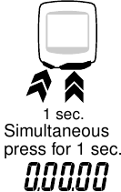
Wheel Setting A and B and Changing the Wheel Setting
The computer has two wheel settings, allowing you to use the unit between two bikes with different size tires. You can tell which WHEEL SETTING you are in by the Wheel Selection Symbol on the screen (Fig. 12).
- Wheel Setting "B" has been specifically programmed for lowspeed sensitivity, and we recommend the use of this setting with your mountain bike.
- To select between Wheel Setting "A" or "B", hold down the SET Button when you are in any function other than the ODOMETER (Odo) function (Fig. 12)
To check the number for the current wheel setting, simultaneously press the ST./STOP(S) Button and the MODE Button when you are in the ODOMETER (Odo) function. While in this status, if you hold down the button for 3 seconds or longer, you can switch between the Wheel Setting "A" and "B" without using the SET Button.
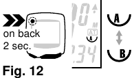
Changing the Wheel Setting Number
- In the ODOMETER function, press the SET Button on the back of the computer. The number for the Wheel Setting will flash on the screen.
- Pressing the MODE Button will increase the number, while pressing the ST./STOP(S) Button will decrease it.
- When the Wheel Setting you would like is displayed, press the SET Button on the back of the computer.
Power Saving Function
When the computer does not receive a signal for approximately 60 to 70 minutes, the computer goes into the power saving mode, and only the CLOCK is displayed. Press either the MODE Button or ST./STOP(S) Button to wake-up the computer.
Maintenance
- When the computer or the contact of bracket gets wet, dry it off with a cloth. Rusting will cause the speed detection error.
- When dirt or small grains of sand get jammed between push buttons and the main unit, push buttons may not be smoothly operated. When this has occurred, just wash them away with water.
Trouble-Shooting
No display
Has the battery in the main unit run out? Replace it with a new one, and do all clear operation.
Incorrect data appears on the screen
Perform the "ALL CLEAR OPERATION". (If possible, take note of the Odo data before performing the "ALL CLEAR OPERATION", and enter it again later.
Current speed does not appear
(When this has occurred, short-circuit the contact of the main unit several times by using a small metal piece. If the speed display appears, the computer is working fine. The problem may be attributed to the bracket or the sensor.)
Is the wire damaged? A damaged wire might not be visible. Replace the bracket sensor with a new one.
Is the distance between the sensor and the magnet too great? Re-adjust the position of the sensor and the magnet. (Clearance: approx. 5 mm)
Is there anything sticking on the contact of the main unit or of the bracket? Clean the contact with a soft cloth.
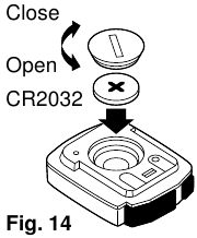
Replacing the Battery
When the display gets lighter, it is the sign of battery replacement. In order to continue the accumulation of Odo data, take note of the data before replacing the battery.
- Insert a new lithium battery (CR2032) with the (+) pole facing up.
![]()
- Perform the ALL CLEAR OPERATION after replacing the battery, and perform necessary setting.
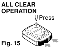
ALL CLEAR OPERATION
Press the SET Button with something like a pen while pressing the MODE and ST./STOP(S) Buttons (fig.15). The entire memory (Odo data, speed scale, wheel setting, and clock time) of the computer will be erased, and the computer is in the distance scale selection mode. Perform this operation when the battery is replaced or in the case of unusual display caused by electrostatics, etc.
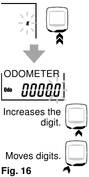
Manually Replacing Mileage (Odo) into Odometer
Although the Odo data returns to zero when the ALL CLEAR OPERA- TION is performed to replace the battery, you can continue to retain the Odo data you have recorded so far, by manually entering the previous Odo data. (Be sure to take note of the data before replacing the battery.)
- After performing the ALL CLEAR OPERATION, select the speed scale by pressing the MODE Button. Then, hold down the MODE Button without pressing the SET Button.(Fig. 16).
![]()
- The Odo and 0000.0 will be displayed, with the flashing digit of 0.1. Enter numbers by pressing the MODE Button, and move digits by pressing the ST./STOP(S) Button. For the Odo data, you can enter up to the 10,000th digit. Display the numbers you noted on the screen, and press the SET Button on the back of the computer. Then, you will be in the Wheel Setting function.
- Set the Wheel Setting in accordance with the description in the section "Setting Up the Computer 3".
Specifications
| Power Supply | Lithium Battery (CR2032) x 1 Battery Life: Approx. 3 years | |
| Controller | 4-bit 1-chip Microcomputer (Crystal Controlled Oscillator) | |
| Display | Liquid Crystal Display | |
| Sensor | No Contact Magnetic Sensor | |
| Length of Wire | 70cm | |
| Applicable Wheel Circumference | 100cm – 300cm | |
| Operating temperature | 32°F – 104°F [0°C – 40°C] | |
| Dimension/Weight | 1-13/16" x 1-17/32" x 9/32" [46 x 39 x 17mm] / 0.92 oz. [26 g] | |
* The life of the factory-loaded battery which comes with the unit may be shorter than this period.
* The specifications and design are subject to change without notice.
LIMITED WARRANTY
2-Year Warranty for Main Unit Only
(Accessories/Attachments and Battery Consumption excluded)
If trouble occurs during normal use, the part of the Main Unit will be repaired or replaced free of charge. The service must be performed by Cat Eye Co., Ltd. To return the product, pack it carefully and remember to enclose the warranty certificate with instruction for repair.
(Address for service)
CAT EYE CO.,LTD.
2-8-25, Kuwazu, Higashi Sumiyoshi-ku, Osaka 546-0041 Japan
Attn.: CAT EYE Customer Service Section
Service & Research Address for United States Consumers: CAT EYE Service & Research Center
1705 14th St. 115 Boulder, CO 80302
Phone: 303-443-4595
Toll Free: 800-5CATEYE
Fax: 303-473-0006
e-mail: service@cateye.com
URL: http://www.cateye.com
#169-9730N
Heavy Duty Wire and Bracket Sensor Kit
#169-6560N [#169-6565N]
Bracket Sensor Kit [Long]
#169-6567 [#169-6562]
Center Mount Bracket Kit [Long]
#169-6568
Bracket Sensor Kit for Aero Bar
#169-6569
Stem Mount Bracket Kit

#169-9752
Attachment Kit
#169-9691
Wheel Magnet

#166-5150
Lithium Battery (CR2032)

#169-6280
Universal Sensor Band
#169-9760
Magnet for Composit Wheel

Documents / Resources
References
Download manual
Here you can download full pdf version of manual, it may contain additional safety instructions, warranty information, FCC rules, etc.
Advertisement


Need help?
Do you have a question about the Enduro 2 and is the answer not in the manual?
Questions and answers