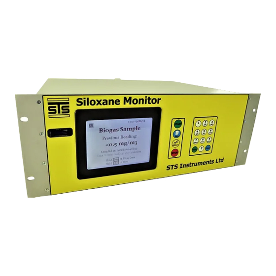
STS Instruments SILOXANE Service Maintenance Manual
Hide thumbs
Also See for SILOXANE:
- Manual (34 pages) ,
- Installation manual (32 pages) ,
- Calibration manual (14 pages)
Summary of Contents for STS Instruments SILOXANE
- Page 1 2018 STS Instruments Ltd, Service & Maintenance Manual SILOXANE MONITOR MANUAL STS INSTRUMENTS COPYRIGHT 2018 STS INSTRUMENTS LTD | www.siloxanemonitoring.com...
-
Page 2: Table Of Contents
7.0 Maintenance Menu ....................11 7.1 Access to menu ....................11 8.0 Fault Identification ..................... 14 8.1 Instrument Error codes ..................14 4-20mA Remote Data Error codes ..............14 9.0 Flow Diagrams ....................15 16/08/2017, STS Instruments Ltd, Service & Maintenance Manual... -
Page 3: Manual Guide
Should at any point you require additional help or information on the use or installation of the system please contact STS directly at: sales@safetrainingsystems.com or +44 (0) 1344 483563 16/08/2017, STS Instruments Ltd, Service & Maintenance Manual... -
Page 4: Safety Information
+44 (0) 1344 483563 3.1 ENVIRONMENTAL PARAMETERS The Siloxane Monitor is not weatherproof and must be housed in a suitable kiosk or cabinet • if sited outside of a building If siting inside a building consideration should be given to the local conditions as regards to •... -
Page 5: Instrumentation Safety Symbols
Gas supply to the instrument should be at a minimum of 200mbar • Adequate ventilation/air passage around the instrument should be provided. • 3.2 INSTRUMENTATION SAFETY SYMBOLS Caution Electrical Hazard Earth Point Hot Surface 16/08/2017, STS Instruments Ltd, Service & Maintenance Manual... -
Page 6: Service Schedule
Heated Line and temperature and measure the temperature inside the insulation using a Weatherproofing temperate probe. Check the insulation for damage and degradation. If damage is present, attempt to repair that section. 16/08/2017, STS Instruments Ltd, Service & Maintenance Manual... - Page 7 Flame Arrestor venting onto a sheet of white paper. Record any residue found. If excessive residue is found replace flame arrestor. Coalescing Filter Note any Discolouration and Moisture. Replace with New Filter. 16/08/2017, STS Instruments Ltd, Service & Maintenance Manual...
- Page 8 Check whether instrument intake and exhaust fans start up upon powering the instrument. If they do not, using a multi-meter, Fans measure the voltage to the fans. If they aren't getting power, return instrument to the manufacturer. 16/08/2017, STS Instruments Ltd, Service & Maintenance Manual...
- Page 9 240degC. If it doesn't, return instrument to manufacturer. To Heaters check the Permeation heater, run a calibration cycle with a temperature probe in the permeation oven. This probe should stabilise around 80degC. If it doesn't return instrument to manufacture. 16/08/2017, STS Instruments Ltd, Service & Maintenance Manual...
- Page 10 Via Maintenance Menu, run a calibration cycle. Leave the first cycle blank, then use 20ul of 1mg/ml D5. Attach Calibration Calibration Report. Adjust the Calibration coefficient to achieve a reading of 20ug. Replace permeation oven seal once finished. 16/08/2017, STS Instruments Ltd, Service & Maintenance Manual...
-
Page 11: Maintenance -Weekly
Check the filter for obvious signs of clogging, should there be any which is not removed by the nitrogen the arrestor should be replaced and the unit returned to STS for overhaul. 6.3 BIOGAS REGULATOR PRESSURE SET 16/08/2017, STS Instruments Ltd, Service & Maintenance Manual... -
Page 12: Heated Line
7.0 MAINTENANCE MENU 7.1 ACCESS TO MENU The maintenance menu can be accessed from the main menu screen: Select: OPTIONS Hold CLEAR on the number pad for approximately 4 secs. 16/08/2017, STS Instruments Ltd, Service & Maintenance Manual... - Page 13 The Maintenance menu screen is displayed Enter the password “SILOX” and press ENTER, START to confirm. Hold 5 to see the View Stats screen 16/08/2017, STS Instruments Ltd, Service & Maintenance Manual...
- Page 14 1. Cleaning 2. Cooldown 3. Sample 4. Purge 5. Background preheat 6. Background 7. Measurement preheat 8. Measurement The internal variables will be displayed on the readout and will change every second. 16/08/2017, STS Instruments Ltd, Service & Maintenance Manual...
-
Page 15: Fault Identification
Error line 4-20mA reading: 0: Standby 25: Communications Fault 50: Fan Fault 75: CH4 High Fault 100: N2 Fault 125: Internal Temp Fault 150: Biogas Volume Fault 175: Concentrator Temp Fault 200: Logging Normally 16/08/2017, STS Instruments Ltd, Service & Maintenance Manual... -
Page 16: Flow Diagrams
9.0 FLOW DIAGRAMS 16/08/2017, STS Instruments Ltd, Service & Maintenance Manual... - Page 17 16/08/2017, STS Instruments Ltd, Service & Maintenance Manual...
- Page 18 16/08/2017, STS Instruments Ltd, Service & Maintenance Manual...
- Page 19 16/08/2017, STS Instruments Ltd, Service & Maintenance Manual...


Need help?
Do you have a question about the SILOXANE and is the answer not in the manual?
Questions and answers