STS Instruments SILOXANE Installation Manual
Hide thumbs
Also See for SILOXANE:
- Manual (34 pages) ,
- Service maintenance manual (19 pages) ,
- Calibration manual (14 pages)

Related Manuals for STS Instruments SILOXANE


Summary of Contents for STS Instruments SILOXANE
- Page 1 STS Instruments Ltd, 2018 Installation Manual SILOXANE MONITOR MANUAL STS INSTRUMENTS LTD COPYRIGHT 2018 STS INSTRUMENTS LTD | www.siloxanemonitoring.com...
-
Page 2: Table Of Contents
3.6 SD Card ......................15 3.7 Data connection line ..................16 3.8 Ancillary Box ....................16 3.9 Remote GSM Data console .................. 16 4.0 Installation ....................... 17 4.1 Ventilation ....................17 August 2017, STS Instruments Ltd, Installation ManualInstallation Manual Jan 2018... - Page 3 4.4.5 Vent ....................... 28 4.4.6 Power ..................... 28 4.4.7 DataComms ....................29 4.4.8 Ancillary Box ..................... 29 4.4.9 Swagelok tube fittings ................. 30 5.0 Post Installation Check list ..................31 August 2017, STS Instruments Ltd, Installation ManualInstallation Manual Jan 2018...
-
Page 4: Manual Guide
Notes required. Should at any point you require additional help or information on the use or installation of the system please contact STS at: sales@safetrainingsystems.com or +44 (0) 1344 483563 August 2017, STS Instruments Ltd, Installation ManualInstallation Manual Jan 2018... -
Page 5: Safety Information
2.0 SAFETY INFORMATION The STS Siloxane Monitor operates from a 110V mains supply, the instrument case should not therefore be opened without having first isolated the power supply and disconnected the kettle lead form the rear of the instrument. The high voltage section of the instrument is protected by clear cover –... -
Page 6: Instrumentation Safety Symbols
The Siloxane Monitor is not weatherproof and must be housed in a suitable kiosk or cabinet • if sited outside of a building If siting inside a building consideration should be given to the local conditions as regards to •... -
Page 7: Overview
Biogas is supplied to the instrument via a sampling system that removes water and particulates. The instrument has been assessed in accordance with IGE SR 25 for potential leakage risk and development of explosive atmospheric conditions internal to the instrument. August 2017, STS Instruments Ltd, Installation ManualInstallation Manual Jan 2018... - Page 8 Any work on the instrument shall be undertaken by a suitably competent person approved for the time being by the Health and Safety Executive. August 2017, STS Instruments Ltd, Installation ManualInstallation Manual Jan 2018...
-
Page 9: Sampling System Design
3.2 SAMPLING SYSTEM DESIGN 3.2.1 SAMPLING SYSTEM SCHEMATICS 3.2.1.1 PRE-FILTER SAMPLE LINE FLOW SCHEMATIC August 2017, STS Instruments Ltd, Installation ManualInstallation Manual Jan 2018... -
Page 10: Sampling System
35mb. If the system pressure has been declared by the operator the installer shall nevertheless verify the site system pressure and selected regulator and ensure that compliance with a 35mb inlet pressure is achieved. August 2017, STS Instruments Ltd, Installation ManualInstallation Manual Jan 2018... -
Page 11: Sampling System Gas Testing
3.2.3 SAMPLING SYSTEM GAS TESTING The siloxane instrument has an isolation valve immediately before the instrument, and immediately after the solenoid valves. The sampling system downstream of the gas regulator shall be tested in accordance with IGE UP1B. -
Page 12: Optional Features
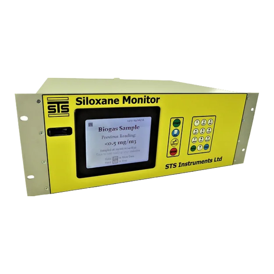
3.4.5 HEATED LINE Used where pipework is run outside of buildings to prevent diurnal fluctuation due to condensation of Siloxanes into pipework – typically 16A. 3.5 KEY COMPONENTS 3.5.1 MONITOR & KIOSK August 2017, STS Instruments Ltd, Installation ManualInstallation Manual Jan 2018... -
Page 13: Regulator
The trap should be located such that it is vertically mounted by means of the fixing bracket at the top of the unit. The trap is powered and activated by the Siloxane Monitor via the Ancillary box which supplies the trap with 24V to operate the solenoid switch. -
Page 14: Coalescing Filter
Where more than 1 sample line is being installed the kiosk is configured with up to 3 electrical operated switching solenoid valves. These valves are orientated such that the normally closed August 2017, STS Instruments Ltd, Installation ManualInstallation Manual Jan 2018... -
Page 15: Heated Line
This should be connected with the gas entering the NO port, the purge being connected to the NC and the instrument to the Common. August 2017, STS Instruments Ltd, Installation ManualInstallation Manual Jan 2018... -
Page 16: Purge Flow Regulator
3.6 SD CARD A standard SD card of 2GB or greater is required. The Instrument will not correctly run without this SD card and will CRASH upon starting a Logging Cycle. August 2017, STS Instruments Ltd, Installation ManualInstallation Manual Jan 2018... -
Page 17: Data Connection Line
12-way (Blue) connector. This box houses an internal area and is preconfigured for each site. Should alteration to the unit be required please contact STS for further information. Danger of electrocution – disconnect from mains supply before opening box. August 2017, STS Instruments Ltd, Installation ManualInstallation Manual Jan 2018... -
Page 18: Installation
4.0 INSTALLATION The siloxane instrument is designed for installation in a building or kiosk, the instrument and sampling system are available pre-mounted in a weather proof kiosk, the container is provided with all necessary vent, drain and power connections. If the instrument is being installed in a building or kiosk that contains other equipment, then it... - Page 19 The Kiosk is ventilated through an open grille to the lower right hand side providing through air ventilation, A thermostatically controlled fan assists in additional ventilation – this is set to operate at temperatures over 10C. August 2017, STS Instruments Ltd, Installation ManualInstallation Manual Jan 2018...
-
Page 20: Pre-Installation
4.2 PRE-INSTALLATION Kiosk siting and fixing down: August 2017, STS Instruments Ltd, Installation ManualInstallation Manual Jan 2018... - Page 21 August 2017, STS Instruments Ltd, Installation ManualInstallation Manual Jan 2018...
-
Page 22: Nitrogen Connection
Nitrogen should be of Technical Grade 99.999% purity. A standard N2 regulator should be fitted to the cylinder and the Special adaptor fitting supplied by STS used to connect the ¼” pipe. August 2017, STS Instruments Ltd, Installation ManualInstallation Manual Jan 2018... -
Page 23: Electrical Setup
4.3 ELECTRICAL SETUP 4.3.1 POWER SUPPLY The Siloxane monitor and ancillaries are designed to run from a 110V centre tapped supply providing 22Amps. Danger of electrocution – isolate from mains supply before working on Electrical circuit. 4.3.2 COMPONENTS The installation comprises an isolator kill switch situated externally on the kiosk, a distribution panel housing a 10A MCB for the heated line, a 10A MCB for the cabinet heater and a 6A MCB for the instrument power. -
Page 24: Certification
4.3.4 CERTIFICATION The electrical installation of the kiosk has been carried out by a suitably qualified electrician to BS7671 and an electrical installation certificate issued. August 2017, STS Instruments Ltd, Installation ManualInstallation Manual Jan 2018... -
Page 25: Heated Line Specification
4.3.5 HEATED LINE SPECIFICATION August 2017, STS Instruments Ltd, Installation ManualInstallation Manual Jan 2018... -
Page 26: Heated Line Installation And Termination Instructions
4.3.6 HEATED LINE INSTALLATION AND TERMINATION INSTRUCTIONS August 2017, STS Instruments Ltd, Installation ManualInstallation Manual Jan 2018... - Page 27 August 2017, STS Instruments Ltd, Installation ManualInstallation Manual Jan 2018...
- Page 28 August 2017, STS Instruments Ltd, Installation ManualInstallation Manual Jan 2018...
-
Page 29: Instrument Connections
Connection to the instrument is by way of a ¼” swagelok bulkhead fitting with retaining lug. Label: VENT 4.4.6 POWER A 3pin kettle lead receptacle with on off switch is located on the rear panel. Label: POWER 110V August 2017, STS Instruments Ltd, Installation ManualInstallation Manual Jan 2018... -
Page 30: Datacomms
A 12 way circular connector is provided for 4-20mV data output. Colour coded BLUE. Label: DATA COMMS 4.4.8 ANCILLARY BOX A 12 way circular connector is provided for ancillary switching services, cabinet fan and water trap power supply. Colour coded RED. Label: ANCILLARY August 2017, STS Instruments Ltd, Installation ManualInstallation Manual Jan 2018... -
Page 31: Swagelok Tube Fittings
4.4.9 SWAGELOK TUBE FITTINGS August 2017, STS Instruments Ltd, Installation ManualInstallation Manual Jan 2018... -
Page 32: Post Installation Check List
Vent line secured at min 3M height – end of line flame arrestor in place Tightness Test Completed Inlet pressure through regulator set at 35mbar max Warning/Advice Labels in place Commissioning guide/quick guide in place August 2017, STS Instruments Ltd, Installation ManualInstallation Manual Jan 2018...
Need help?
Do you have a question about the SILOXANE and is the answer not in the manual?
Questions and answers