Chapters
Table of Contents

Related Manuals for Stanley 78200-010040


Summary of Contents for Stanley 78200-010040
- Page 1 INSTRUCTION AND SERVICE MANUAL ORIGINAL INSTRUCTION Hydro-Pneumatic Power Tool Hydropneumatisches Setzgerät 78200-010040 Mini MBS Workstation for Speed Rivets Hydro-Pneumatic Power Tool...
-
Page 2: Table Of Contents
STANLEY Engineered Fastening. The information provided is based on the data known at the moment of the introduction of this product. STANLEY Engineered Fastening pursues a policy of continuous product improvement and therefore the products may be subject to change. The information provided is applicable to the product as delivered by STANLEY Engineered Fastening. - Page 3 O R I G I N A L I N S T R U C T I O N E N G L I S H 4.3.2 SETTING THE WORKING PRESSURE 4.3.3 ADJUSTING THE RETURN STROKE AT THE PRESSURE INTENSIFIER LOADING THE SPEED FASTENER MODULES 4.4.1 CURSOR 4.4.2 LOADING THE MANDREL...
-
Page 4: Safety Definitions
NOTE: The Mini MBS Workstation for Speed Rivets may only be used for the intended purpose. NOTE: Should you have any questions concerning plant and operator safety, please contact STANLEY Engineered Fastening. SAVE ALL WARNINGS AND INSTRUCTIONS FOR FUTURE REFERENCE 1.1 GENERAL SAFETY RULES... -
Page 5: Projectile Hazards
O R I G I N A L I N S T R U C T I O N E N G L I S H 1.2 PROJECTILE HAZARDS • Disconnect the tool from the pneumatic supply before performing any maintenance, attempting to adjust, fi t or remove a nose assembly or accessories. -
Page 6: Noise Hazards
E N G L I S H O R I G I N A L I N S T R U C T I O N 1.7 NOISE HAZARDS • Exposure to high noise levels can cause permanent, disabling hearing loss and other problems, such as tinnitus (ringing, buzzing, whistling or humming in the ears). -
Page 7: Personnel Requirements
• Repair STANLEY Engineered Fastening policy is one of continuous product development and improvement and we reserve the right to change the specifi cation of any product without prior notice. WARNING: While a small amount of wear and marking will naturally occur through normal and correct use of mandrels, they must be regularly examined for excessive wear and marking, with particular attention to the head diameter, the tail jaw gripping area of the shank or heavy pitting of the shank and any mandrel distortion. -
Page 8: Specification
E N G L I S H O R I G I N A L I N S T R U C T I O N 2. SPEC IFICATION 2.1 78200-010040 WORKSTATION SPECIFICATION Air Pressure Minimum – Maximum 5-6 bar (70-87 lbf/in... -
Page 9: 70500-02000 Module Specification
CUSTOMER SPECIFIC PN MANDREL SPRING The riveting equipment is exclusively intended for place Ø2.4 to Ø6.4 STANLEY Engineered Fastening speed fasteners and should only be used for this purpose. Only Riveting Equipment manufactured by STANLEY Engineered Fastening must be used. -
Page 10: Pneumatic Control
E N G L I S H O R I G I N A L I N S T R U C T I O N 2.3 PNEUMATIC CONTROL Part Number 78200-010073 PC Circuit Diagram Refer to drawing 78200-010073 PC Pneumatic Pressure Inlet 6 bar (87 lbf/in... -
Page 11: Intent Of Use
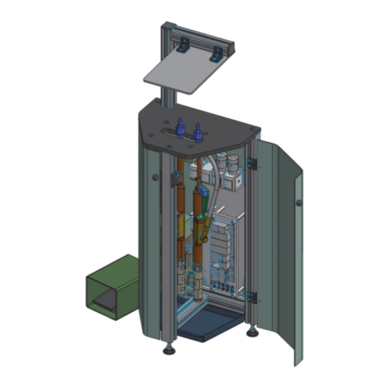
3. INTENT OF USE The pneumatic Mini MBS Workstation is designed to place STANLEY Engineered Fastening speed fasteners of the sizes Ø2.4 to Ø6.4 making it ideal for batch or fl ow-line assembly in a wide variety of applications throughout all industries. - Page 12 E N G L I S H O R I G I N A L I N S T R U C T I O N ITEM PART NUMBER DESCRIPTION 70500-02000 70500 SPEED FASTENER MODULE REFER TO ASSEMBLY DRAWING SAFEGUARD WITH PROTECTIVE COVER REFER TO ASSEMBLY DRAWING RETAINING PLATE REFER TO ASSEMBLY DRAWING...
-
Page 13: Arrangement Of Control Elements
O R I G I N A L I N S T R U C T I O N E N G L I S H 3.2 ARRANGEMENT OF CONTROL ELEMENTS 3.0 / 2.6 ITEM PART NUMBER DESCRIPTION ROLLER LEVER VALVE MANDREL CLAMP – REFER TO ASSEMBLY DRAWING SAFEGUARD REFER TO ASSEMBLY DRAWING... -
Page 14: Putting Into Service
E N G L I S H O R I G I N A L I N S T R U C T I O N 4. PUTTING INTO SERVICE IMPORTANT When selecting the site, due consideration should be given to allowing suffi cient space to provide access to the Mini MBS Workstation for maintenance and repair purposes. -
Page 15: How To Connect The Hydraulic System
O R I G I N A L I N S T R U C T I O N E N G L I S H ► Connect the serially numbered pneumatic hoses PUN-4 (5) and (6) to the threaded unions on the pneumatic control. -
Page 16: Pressure Intensifier
E N G L I S H O R I G I N A L I N S T R U C T I O N 4.2.1 PRESSURE INTENSIFIER IMPORTANT Danger of damage to property and malfunctions! Remove the blind plug on the pressure intensifi er in the pneumatic control. Step 1 ►... -
Page 17: Pressure Settings
O R I G I N A L I N S T R U C T I O N E N G L I S H ► Check oil level gauge (4). The oil level must be fi lled to at least 2/3 of the maximum capacity. -
Page 18: Loading The Speed Fastener Modules
E N G L I S H O R I G I N A L I N S T R U C T I O N 4.4 LOADING THE SPEED FASTENER MODULES 4.4.1 CURSOR IMPORTANT If fi tted incorrectly, the cursor will not allow feeding of the fasteners. While the cursor will be fi tted the correct way round when the tool is supplied, we recommend that you check its orientation before fi tting the nose equipment. -
Page 19: Operating Procedure
O R I G I N A L I N S T R U C T I O N E N G L I S H If you have been supplied with a nose jaw, mandrels and mandrel follower springs proceed with loading the tool and fi tting the nose equipment as follows. -
Page 20: Placing Equipment
It is the customer’s obligation to examine the full extent of the delivery on receipt for any transport damage and where necessary, to report this to STANLEY Engineered Fastening. Transport damages must be documented (for example, by taking pictures) to be reproducible and recoverable at a later time. -
Page 21: Servicing The Tool
Yearly or every 500,000 cycles • Full inspection and service of the complete Mini MBS Workstation by STANLEY Engineered Fastening representative. If any malfunctions or diffi culties during operation occur, please consult STANLEY Engineered Fastening. 5.2 MOLY LITHIUM GREASE EP 3753 - SAFETY DATA Grease can be ordered as a single item using part number 07992-00020. - Page 22 E N G L I S H O R I G I N A L I N S T R U C T I O N HANDLING Use barrier cream or oil resistant gloves STORAGE Away from heat and oxidising agent.
-
Page 23: Maintenance
Maintenance work primarily concerns the speed fastener module 70500-02000 as well as the riveting equipment 6.1 DISMANTLING 70500-02000 For full instructions on the service and maintenance of the placing module 70500-02000 refer to the STANLEY Engineered Fastening Instruction Manual 07900-09704 that is supplied with the Mini MBS Workstation documentation. -
Page 24: Priming
Wear eye protection, impervious gloves (e.g. of PVC) and a plastic apron. Use in well ventilated area. STORAGE No special precautions. 7.2 PRIMING PROCEDURE For priming instructions on the placing module 70500-02000 refer to the STANLEY Engineered Fastening Instruction Manual 07900-09704 that is supplied with the Mini MBS Workstation documentation. -
Page 25: Fault Diagnosis
O R I G I N A L I N S T R U C T I O N E N G L I S H 8. FAULT DIAGNOSIS Symptom Possible Cause Remedy Low air pressure. Increase air pressure Lack of lubrication. Lubricate tool at air inlet point High broach load. -
Page 26: Disposal
To avoid damage to the environment, we recommend having authorized specialist companies to dispose of these components. A free of charge return to STANLEY Engineered Fastening is not agreed. Should you have any questions on legislation concerning proper disposal and environment issues, please contact STANLEY Engineered Fastening. -
Page 27: Ec Declaration Of Conformity
Date of Issue: 01-01-2022 The undersigned is responsible for compilation of the technical fi le for products sold in the European Union and makes this declaration on behalf of Stanley Engineered Fastening. Matthias Appel Team Leader Technical Documentation Stanley Engineered Fastening, Tucker GmbH, Max-Eyth-Str.1, 35394 Gießen, Germany... -
Page 28: Declaration Of Conformity
Stanley Engineered Fastening. A. K. Seewraj Director of Engineering, UK Avdel UK Limited, Stanley House, Works Road, Letchworth Garden City, Hertfordshire, SG6 1JY UNITED KINGDOM This machinery is in conformity with Supply of Machinery (Safety) Regulations 2008,... -
Page 29: Protect Your Investment
Engineered Fastening location. STANLEY Engineered Fastening will then replace, free of charge, any part or parts found by us to be defective due to faulty material or workmanship and return the tool prepaid. This represents our sole obligation under this warranty. -
Page 30: Third-Party Documentation
E N G L I S H O R I G I N A L I N S T R U C T I O N 13. THIRD-PARTY DOCUMENTATION 13.1 PRESSURE INTENSIFIER Model/Type: Assembly Drawing and Bill of Materials Manufacturer: Reiplinger GmbH Im Voigtstedter Feld 2 D-06528 Edersleben... - Page 31 O R I G I N A L I N S T R U C T I O N E N G L I S H Pressure Intensifi er General Assembly Drawing...
-
Page 32: Mini Mbs Workstation Drawings
O R I G I N A L I N S T R U C T I O N 14. MINI MBS WORKSTATION DRAWINGS 14.1 MINI MBS WORKSTATION GENERAL ASSEMBLY DRAWING Model/Type: General Assembly Drawing Designation: Fastener Riveting Station Mini-MBS Part No.: 78200-010040 Format: DIN A 0 Contents: 1 page Remarks: List of Amendments Change Ref. Name... - Page 33 O R I G I N A L I N S T R U C T I O N E N G L I S H...
-
Page 34: Pneumatic Circuit Diagram
E N G L I S H O R I G I N A L I N S T R U C T I O N 14.2 PNEUMATIC CIRCUIT DIAGRAM Model/Type: Pneumatic Circuit Drawing Designation: MINI MBS Pneumatic Circuit Part No.: 78201-010073 PC Format: DIN A 1... - Page 35 O R I G I N A L I N S T R U C T I O N E N G L I S H...
- Page 36 Produktverbesserung und somit können die Produkte Änderungen unterliegen. Die bereitgestellten Informationen gelten für das Produkt wie von STANLEY Engineered Fastening geliefert. Daher haftet STANLEY Engineered Fastening nicht für Schäden, die aus Abweichungen von den ursprünglichen Spezifi kationen des Produkts entstehen.
- Page 37 ÜBERSETZUNG DER ORIGINALANLEITUNG DEUTSCH 4.3.1 EINSTELLEN DES EINGANGSDRUCKS 4.3.2 EINSTELLEN DES BETRIEBSDRUCKS 4.3.3 EINSTELLEN DES RÜCKHUBS AM DRUCKVERSTÄRKER LADEN DER SCHNELLBEFESTIGERMODULE 4.4.1 SCHIEBER 4.4.2 LADEN DES ZIEHDORNS 4.4.3 LADEN DES SCHNELLBEFESTIGERMODULS BEDIENUNGSSCHRITTE SETZAUSRÜSTUNG LAGERUNG UND TRANSPORT WARTUNG DES WERKZEUGS WARTUNGSINTERVALL SICHERHEITSDATEN ZU MOLY-LITHIUM-FETT EP 3753 INSTANDHALTUNG DEMONTAGE 70500-02000...
-
Page 38: Sicherheitsdefinitionen
HINWEIS: Die Mini MBS Workstation für Schnellniete darf nur für den vorgesehenen Zweck verwendet werden. HINWEIS: Bei Fragen zur Anlagen- und Bedienersicherheit wenden Sie sich bitte an STANLEY Engineered Fastening. BEWAHREN SIE ALLE WARNHINWEISE UND ANWEISUNGEN ZUM SPÄTEREN NACHSCHLAGEN AUF 1.1 ALLGEMEINE SICHERHEITSBESTIMMUNGEN... -
Page 39: Gefahren Durch Umherfliegende Teile
ÜBERSETZUNG DER ORIGINALANLEITUNG DEUTSCH • Prüfen Sie vor der Verwendung, ob bewegliche Teile verzogen oder ausgeschlagen, ob Teile gebrochen oder in einem Zustand sind, der den Betrieb des Werkzeugs beeinträchtigt. Bei Beschädigungen lassen Sie das Werkzeug warten, bevor Sie es verwenden. Entfernen Sie vor dem Gebrauch alle Einstellwerkzeuge oder Schraubenschlüssel. •... -
Page 40: Gefahren Am Arbeitsplatz
DEUTSCH ÜBERSETZUNG DER ORIGINALANLEITUNG 1.6 GEFAHREN AM ARBEITSPLATZ • Ausrutschen, Stolpern und Stürzen sind die Hauptursachen für Verletzungen am Arbeitsplatz. Achten Sie auf rutschige Oberfl ächen, die durch den Einsatz des Werkzeugs verursacht werden, sowie auf Stolperfallen durch die Luftleitung oder den Hydraulikschlauch. -
Page 41: Sorgfaltspflicht Des Betreiberunternehmens
Verantwortung des Kunden, dafür zu sorgen, dass die Dorne vor dem Auftreten von übermäßigem Verschleiß und stets vor der maximal empfohlenen Anzahl von Setzvorgängen ausgetauscht werden. Wenden Sie sich an Ihren Vertreter von STANLEY Engineered Fastening, der Ihnen diese Werte mitteilen kann, indem er die Räumnadelkraft Ihrer Anwendung mit unserem kalibrierten Messwerkzeug misst. -
Page 42: Technische Daten
DEUTSCH ÜBERSETZUNG DER ORIGINALANLEITUNG 2. TECHNISCH E DATEN 2.1 78200-010040 WORKSTATION – TECHNISCHE DATEN Luftdruck Minimum – Maximum 5-6 bar (70-87 lbf/in Hydraulikdruck Maximum 120 bar (1741 lbf/in Hydraulikfl üssigkeit Technische Daten Castrol Hyspin VG32 Volumen der Hydraulikfl üssigkeit Ungefähr... -
Page 43: 70500-02000 Technische Daten Des Moduls
DORN KUNDENSPEZIFISCHE TN ZIEHDORNFEDER Die Nietausrüstung ist ausschließlich zum Setzen von STANLEY Engineered Fastening Schnellbefestigern mit Ø2,4 bis Ø6,4 bestimmt und darf nur für diesen Zweck verwendet werden. Es dürfen nur von STANLEY Engineered Fastening hergestellte Nietausrüstung verwendet werden. 2.4 DRUCKVERSTÄRKER... -
Page 44: Pneumatiksteuerung
DEUTSCH ÜBERSETZUNG DER ORIGINALANLEITUNG 2.3 PNEUMATIKSTEUERUNG Teilenummer 78200-010073 PC Schaltplan Siehe Zeichnung 78200-010073 PC Luftdruck Einlass 6 bar (87 lbf/in Den Pneumatikschaltplan fi nden Sie in der Zeichnung auf Seite 68. -
Page 45: Verwendungszweck
DEUTSCH 3. VERWENDUNGSZWECK Die pneumatische Mini MBS Workstation ist zum Setzen von STANLEY Engineered Fastening Schnellbefestigern der Größe Ø2,4 bis Ø6,4 vorgesehen, wodurch es sich ideal für die Chargen- oder Fließmontage in einer Vielzahl von Anwendungen in allen Branchen eignet. - Page 46 DEUTSCH ÜBERSETZUNG DER ORIGINALANLEITUNG POSITION ARTIKELNUMMER BESCHREIBUNG 70500-02000 70500 SCHNELLBEFESTIGERMODUL SIEHE MONTAGEZEICHNUNG SICHERUNG MIT SCHUTZABDECKUNG SIEHE MONTAGEZEICHNUNG HALTEPLATTE SIEHE MONTAGEZEICHNUNG EINSTELLEINHEIT SIEHE MONTAGEZEICHNUNG EINSTELLSCHLITTEN SIEHE MONTAGEZEICHNUNG SPANNHEBEL SIEHE MONTAGEZEICHNUNG ROLLENVENTILEINHEIT SIEHE MONTAGEZEICHNUNG DRUCKREGLER SIEHE MONTAGEZEICHNUNG FUSSPEDALAUSLÖSER 78201-010073 PC PNEUMATIKSTEUERUNGSSYSTEM DU100/22 H65 RS DRUCKVERSTÄRKER SIEHE MONTAGEZEICHNUNG ALUMINIUM-GRUNDRAHMEN...
-
Page 47: Anordnung Der Bedienelemente
ÜBERSETZUNG DER ORIGINALANLEITUNG DEUTSCH 3.2 ANORDNUNG DER BEDIENELEMENTE 3.0 / 2.6 POSITION ARTIKELNUMMER BESCHREIBUNG SIEHE MONTAGEZEICHNUNG ROLLENHEBELVENTIL-DORNSPANNUNG – SICHERUNG SIEHE MONTAGEZEICHNUNG FUSSPEDALSCHALTER – NIETENTRIEGELUNG SIEHE MONTAGEZEICHNUNG DRUCKREGLER – RÜCKHUB – EINGANGSDRUCK SIEHE MONTAGEZEICHNUNG DRUCKREGLER – ARBEITSDRUCK SIEHE MONTAGEZEICHNUNG DRUCKREGLER – EINGANGSDRUCK Den Pneumatikschaltplan fi nden Sie in der Zeichnung auf Seite 68. -
Page 48: Inbetriebnahme
DEUTSCH ÜBERSETZUNG DER ORIGINALANLEITUNG 4. INBETRIEBNAHME WICHTIG Bei der Auswahl des Standorts sollte auf genügend Platz geachtet werden, um den Zugang zur Mini MBS Workstation für Wartungs- und Reparaturzwecke zu ermöglichen. Für die Wahl des Aufstellungsorts ist der Betreiber verantwortlich. Der Platzbedarf für die Befestigungsmittel-Nietstation Mini MBS muss entsprechend den Angaben im Kapitel „Technische Daten“... -
Page 49: Anschliessen Des Hydrauliksystems
ÜBERSETZUNG DER ORIGINALANLEITUNG DEUTSCH Der Fußpedalauslöser muss über zwei Pneumatikschläuche PUN-4 pneumatisch mit der Pneumatiksteuerung verbunden werden. ► Schließen Sie die durchnummerierten Pneumatikschläuche PUN-4 (5) und (6) an die Armaturen der Pneumatiksteuerung an. 4.1.3 ANSCHLIESSEN DES HYDRAULIKSYSTEMS Die Versorgungsleitungen müssen für den maximalen Systemdruck ausgelegt sein und einen ausreichenden Durchfl uss für die Betriebsfl üssigkeiten gewährleisten! Achten Sie darauf, dass die Schläuche weder geknickt noch gequetscht oder in irgendeiner Weise beschädigt sind. -
Page 50: Druckverstärker
DEUTSCH ÜBERSETZUNG DER ORIGINALANLEITUNG 4.2.1 DRUCKVERSTÄRKER WICHTIG Gefahr von Sachschäden und Fehlfunktionen! Entfernen Sie den Blindstopfen am Druckverstärker in der Pneumatiksteuerung. Schritt 1 ► Entfernen Sie den Blindstopfen (1) am Druckverstärker (2) mit einem M6-Innensechskantschlüssel. Schritt 2 ► Schrauben Sie den beiliegenden Öldeckel (3) in den Druckverstärker (2). -
Page 51: Druckeinstellungen
ÜBERSETZUNG DER ORIGINALANLEITUNG DEUTSCH ► Prüfen Sie die Ölstandsanzeige (4). Der Ölstand muss mindestens 2/3 des maximalen Füllstands betragen. 4.3 DRUCKEINSTELLUNGEN 4.3.1 EINSTELLEN DES EINGANGSDRUCKS ► Stellen Sie den Eingangsdruck am Druckregler 3.0 auf max. 6 bar ein. 4.3.2 EINSTELLEN DES BETRIEBSDRUCKS ►... -
Page 52: Laden Der Schnellbefestigermodule
DEUTSCH ÜBERSETZUNG DER ORIGINALANLEITUNG 4.4 LADEN DER SCHNELLBEFESTIGERMODULE 4.4.1 SCHIEBER WICHTIG Bei falscher Montage lässt der Schieber die Zuführung der Befestigungsmittel nicht zu. Obwohl der Schieber bei der Lieferung des Werkzeugs richtig herum eingesetzt ist, empfehlen wir Ihnen, seine Ausrichtung zu überprüfen, bevor Sie das Mundstück montieren. -
Page 53: Bedienungsschritte
ÜBERSETZUNG DER ORIGINALANLEITUNG DEUTSCH Wenn Sie über Mundstückbacken, Dornen und Dornfolgefedern verfügen, fahren Sie mit dem Laden des Werkzeugs und der Montage der Nietausrüstung wie nachfolgend gezeigt fort. LADEN DES WERKZEUGS • Luftversorgung an das Werkzeug anschließen. • Öff nen Sie die Schutzhaube wie oben gezeigt. Der Nieteingangsdruck wird abgeschaltet und die Endbacken, die den Ziehdorn greifen, öff nen sich zeitverzögert. -
Page 54: Setzausrüstung
• Die Mini MBS Workstation darf nicht mit unvollständiger Ausrüstung betrieben werden. • Die Kombination aus Niet, Ziehdorn, Materialstärke und Lochgröße muss den von STANLEY Engineered Fastening defi nierten Spezifi kationen entsprechen. • Setzen Sie das zu befestigende Bauteil auf die Mini MBS Workstation und drücken Sie die aus den beiden Mundstückbacken herausragenden Befestiger vollständig in die Anwendungslöcher, damit die Anwendung... -
Page 55: Wartung Des Werkzeugs
Dazu das Öl Castrol Hyspin VG32 verwenden. Jährlich oder alle 500.000 Zyklen • Vollständige Inspektion und Wartung der kompletten Mini MBS Workstation durch einen Vertreter von STANLEY Engineered Fastening durchführen lassen. Sollten beim Betrieb Funktionsstörungen oder Schwierigkeiten auftreten, wenden Sie sich bitte an STANLEY Engineered Fastening. - Page 56 DEUTSCH ÜBERSETZUNG DER ORIGINALANLEITUNG BRAND FLAMMPUNKT: Über 220°C. Nicht als brennbar eingestuft. Geeignete Löschmittel: CO , Halon oder Wasserspray, wenn von einem erfahrenen Betreiber angewendet. UMWELT Zusammenkratzen und zur Verbrennung oder Entsorgung zur zugelassenen Stelle bringen. HANDHABUNG Schutzcreme oder ölfeste Handschuhe verwenden LAGERUNG Von Hitze und Oxidationsmitteln fernhalten.
-
Page 57: Instandhaltung
Die Wartungsarbeiten betreff en in erster Linie das Schnellbefestigermodul 70500-02000 sowie die Nietausrüstung. 6.1 DEMONTAGE 70500-02000 Ausführliche Anweisungen zur Wartung und Instandhaltung des Setzmoduls 70500-02000 fi nden Sie in der STANLEY Engineered Fastening Betriebsanleitung 07900-09704, die mit der Dokumentation der Mini MBS Workstation geliefert wird. -
Page 58: Auffüllen
Augenschutz, undurchlässige Handschuhe (z. B. aus PVC) und eine Kunststoff schürze tragen. In gut belüftetem Bereich verwenden. LAGERUNG Keine besonderen Vorkehrungen. 7.2 AUFFÜLLEN Anweisungen zum Auff üllen des Setzmoduls 70500-02000 fi nden Sie in der STANLEY Engineered Fastening Betriebsanleitung 07900-09704, die mit der Dokumentation der Mini MBS Workstation geliefert wird. -
Page 59: Fehlersuche
ÜBERSETZUNG DER ORIGINALANLEITUNG DEUTSCH 8. FEHLERSUCHE Symptom Mögliche Ursache Abhilfe Ungenügender Luftdruck. Luftdruck erhöhen Fehlende Schmierung. Werkzeug am Lufteinlasspunkt schmieren Griffi gkeit des Befestigungsmittels und die Hohe Räumnadelbelastung. Größe des Anwendungslochs prüfen Werkzeug setzt keine Befestigungsmittel Auf richtige Größe des Dorns prüfen. Befestigungsmittel Abgenutzte oder gebrochene Endbacken. -
Page 60: Entsorgung
Zur Vermeidung von Umweltschäden empfehlen wir, diese Bauteile von autorisierten Fachbetrieben entsorgen zu lassen. Eine kostenfreie Rücksendung an STANLEY Engineered Fastening ist nicht vereinbart. Bei Fragen zur Gesetzgebung in Bezug auf die ordnungsgemäße Entsorgung und Umweltfragen wenden Sie sich bitte an... -
Page 61: Ec-Konformitätserklärung
01-01-2022 Ausstellung: Der Unterzeichnete ist verantwortlich fur die Zusammenstellung des technischen Dossiers fur Produkte, die in der Europaischen Union verkauft werden, und gibt diese Erklarung im Namen von Stanley Engineered Fastening ab. Matthias Appel Teamleiter Technische Dokumentation Stanley Engineered Fastening, Tucker GmbH, Max-Eyth-Str.1,... -
Page 62: Konformitätserklärung
01-01-2022 Ausstellung: Der Unterzeichnete ist verantwortlich fur die Zusammenstellung des technischen Dossiers fur Produkte, die in GroBbritannien verkauft werden, und gibt diese Erklarung im Namen von Stanley Engineered Fastening ab. A. K. Seewraj Director of Engineering, UK Avdel UK Limited, Stanley House, Works Road, Letchworth Garden City, Hertfordshire,... -
Page 63: Schützen Sie Ihre Investition
Verarbeitung als defekt festgestellt wurden und das Werkzeug mit bezahlten Versandkosten zurücksenden. Das ist unsere einzige Verpfl ichtung unter dieser Garantie. In keinem Fall ist STANLEY® Engineered Fastening haftbar für irgendwelche Folge- oder speziellen Schäden, die aus dem Kauf oder der Verwendung dieses Werkzeugs entstehen. -
Page 64: Dokumentation Von Drittanbietern
DEUTSCH ÜBERSETZUNG DER ORIGINALANLEITUNG 13. DOKUMENTATION VON DRITTANBIETERN 13.1 DRUCKVERSTÄRKER Modell/Typ: Montagezeichnung und Materialliste Hersteller: Reiplinger GmbH Im Voigtstedter Feld 2 D-06528 Edersleben Deutschland Bezeichnung: Druckverstärker Teile-Nr.: DU100/22 H65 RS Modell: Modell DU100/22 H65 RS Format: DIN A 4 Inhalt: 3 Seiten Datum: 10/2003 Teileliste für den Druckverstärker... - Page 65 ÜBERSETZUNG DER ORIGINALANLEITUNG DEUTSCH Druckverstärker – Allgemeine Montagezeichnung...
-
Page 66: Mini Mbs Workstation - Zeichnungen
DEUTSCH ÜBERSETZUNG DER ORIGINALANLEITUNG 14. MINI MBS WORKSTATION – ZEICHNUNGEN 14.1 MINI MBS WORKSTATION – ALLGEMEINE MONTAGEZEICHNUNG Modell/Typ: Allgemeine Montagezeichnung Bezeichnung: Befestigungsmittel-Nietstation Mini MBS Teile-Nr.: 78200-010040 Format: DIN A 0 Inhalt: 1 Seite Hinweise: Liste der Änderungen Änderungsref. Name Datum Bezeichnung... - Page 67 ÜBERSETZUNG DER ORIGINALANLEITUNG DEUTSCH...
-
Page 68: Pneumatikschaltplan
DEUTSCH ÜBERSETZUNG DER ORIGINALANLEITUNG 14.2 PNEUMATIKSCHALTPLAN Modell/Typ: Pneumatikschaltplanzeichnung Bezeichnung: MINI MBS Pneumatikschaltplan Teile-Nr.: 78201-010073 PC Format: DIN A 1 Inhalt: 1 Seite Hinweise: Liste der Änderungen Änderungsref. Name Datum Bezeichnung... - Page 69 ÜBERSETZUNG DER ORIGINALANLEITUNG DEUTSCH...
- Page 70 DEUTSCH ÜBERSETZUNG DER ORIGINALANLEITUNG...
- Page 71 ÜBERSETZUNG DER ORIGINALANLEITUNG DEUTSCH...
- Page 72 For an authorized distributor nearby please check www.stanleyEngineeredFastening.com/econtact/distributors Manual Number Issue 07900-09801 22/078 Stanley Engineered Fastening — a division of Stanley Black and Decker — is the global leader in precision fastening and assembly solutions. Our industry-leading brands, Avdel ® , Integra ™ , Nelson ®...
Need help?
Do you have a question about the 78200-010040 and is the answer not in the manual?
Questions and answers