Table of Contents
Advertisement
Quick Links
Advertisement
Table of Contents

Related Manuals for Panasonic TZ-PCD2000


Summary of Contents for Panasonic TZ-PCD2000
-
Page 1: Operating Instructions
Digital CATV Terminal Operating Instructions TZ-PCD2000 Model No. For assistance, please call : your regional operator (installer) Before connecting, operating or adjusting this product, please read these instructions completely. Save this manual for future reference. TQB2AA0369... -
Page 2: Note To Catv System Installer
WARNING: To reduce the risk of electric shock do not remove cover or back. No user-serviceable parts inside. Refer servicing to qualified service personnel. The lightning flash with arrow-head within a triangle is intended to tell the user that parts inside the product are a risk of electric shock to persons. -
Page 3: Additional Instructions
Additional Instructions Power Sources This product shall be operated only from the type of power source indicated on the marking label. If you are not sure of the type of power supply to your home, consult your Cable operator or Digital CATV Terminal installer or local power company. -
Page 4: Care And Cleaning
Additional Instructions Outdoor Antenna Grounding If an outside antenna or cable system is connected to the product, be sure the antenna or cable system is grounded so as to provide some protection against voltage surges and built-up static charges. Article 810 of the National Electrical Code, ANSI/NFPA 70, provides information with regard to proper grounding of the mast and supporting structure, grounding of the lead-in wire to an antenna discharge unit, size of grounding conductors, location of antenna-discharge unit, connection to grounding electrodes, and requirements for the grounding electrode. -
Page 5: Fcc Statement
Digital CATV Terminal not expressly approved by Matsushita Electric Corporation of America could cause harmful interference and would void the user’s authority to operate this device. PANASONIC CONSUMER ELECTRONICS COMPANY Responsible party: Matsushita Electric Corporation of America... -
Page 6: Table Of Contents
Dear Panasonic Customer Welcome to the Panasonic Family of customers. We hope that you have many years of enjoyment from your new Digital CATV Terminal. To obtain maximum benefit from your set, please read these Instructions before making any adjustments, and retain them for future reference. -
Page 7: Installation
Installation ACCESSORIES Check the accessories before installations. Operating Instruction book Remote Control battery installation Requires two AA batteries. 1. Push the section marked with an arrow while lifting the cover up to open it. Precaution on battery use Incorrect installation can cause battery leakage and corrosion that will damage the remote control transmitter. Observe the following precautions: 1. -
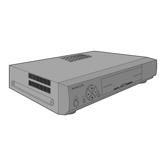
Page 8: Front And Rear View Of The Digital Catv Terminal
Installation Front and Rear View of the Digital CATV Terminal Front Panel POWER indicator(LED) Volume - Button Channel + Button Volume + Button Channel - Button Power Button Factory use only POWER Turns the Digital CATV Terminal Power On or Off. VOL +- Select Volume Up or Down CH +-... - Page 9 Rear Panel AUDIO jacks DATA Port S-VIDEO jack USB(Universal Serial Bus) Port CABLE IN Use to connect Cable Signal from Cable Service Provider. CABLE OUT Use to connect the Digital CATV Terminal to your TV or VCR. VIDEO Use to connect the Digital CATV Terminal to your TV or VCR. S-VIDEO Use to connect the Digital CATV Terminal to your TV with S-VIDEO, or VCR with S-VIDEO.
-
Page 10: Cable Connection
Installation Cable connection Connect the cable wire to the CABLE IN jack on the rear panel of the Digital CATV Terminal. Unplug the AC power cord and disconnect all cables attached to the Digital CATV Termi- nal. Digital CATV Terminal connection to stereo TV and stereo VCR Follow this diagram when connecting the Digital CATV Terminal to a stereo TV and stereo VCR. -
Page 11: Digital Catv Terminal Connection To Tv And Vcr
Digital CATV Terminal connection to TV and VCR Follow this diagram when connecting the Digital CATV Terminal to a TV and VCR. VCR or S-VCR Procedure Connect the CABLE OUT jack of the Digital CATV Terminal to the ANT IN jack of the VCR, and connect the ANT OUT jack of the VCR to the ANT IN jack of the TV using 75 Connecting a non-cable ready TV TV Set UHF Antenna... -
Page 12: Digital Catv Terminal Connection To Component With Digital Audio Input Jack
Installation Digital CATV Terminal connection to component with Digital Audio Input jack Follow this diagram to connect the Digital CATV Terminal to a component with a Digital Audio Input jack. Procedure Connect the Digital Audio Cable from the Digital Audio Out jack on the Digital CATV Terminal to the Digital Audio Input jack on the component with the Digital Audio Input jack. -
Page 13: Power On/Off
VCR output channel (channel 3 or 4). Note: If using a non-Panasonic brand TV, make the selection directly at the TV itself, or use the TV’s remote control to make the setting as described on page 17. -
Page 14: Remote Control
Remote Control CBL, TV, VCR, AUX Press to select remote operation. POWER Press to turn ON and OFF. Press to move through interactive screen choices. SELECT Press to choose interactive screen item. Page Press to display Next/Previous screen. A, B, C On-Screen decision buttons Press to select channel Up/Down Mute... -
Page 15: Remote Control Function Key Chart
The description of functions for each of the components in the table above apply when the factory default code settings are in place. The factory default code settings are as follows: TV:Panasonic brand TV (code: 0250) VCR:Panasonic-brand VCR (code: 1062) - Page 16 The description of functions for each of the components in the table above apply when the factory default code settings are in place. The factory default code settings are as follows: TV:Panasonic brand TV (code: 0250) VCR:Panasonic-brand VCR (code: 1062)
-
Page 17: Programming The Remote Control
User’s Guide which is supplied with the VCR Commander package. At the time of shipment from the factory, the code is set to Panasonic-brand VCRs (code: 1062). Use the following procedure to program the VCR or DVD player remote control code. -
Page 18: Name Of Component
Programming the Remote Control Programming Without Code If you cannot find the right Code, you can call up all Codes one after the other to search for a Code. 1.Turn on the power for the Component to be programmed. 2.Press the mode button (TV, VCR or AUX) for the component to be programmed, POWER button 3.Use the numeric buttons on the remote control to enter “991”. -
Page 19: Mode Reassignment
Programming for volume control The volume adjustment function can be locked so that regardless of whether CBL, TV or VCR mode is active, the volume is adjusted for only one of the modes. (Refer to table below.) The default setting is TV. When the setting is AUX mode, you can adjust the volume for the AUX component at all times, even if some other mode is currently active. -
Page 20: Changing Button Functions
Programming the Remote Control Changing button functions The functions of the remote control buttons can be assigned to other buttons. Setting method (Example) Assigning the function of the POWER button in TV mode to the Exit button in VCR mode 1.Press the Setup button and hold for 3 seconds (until the visible LED blinks twice). -
Page 21: Component Codes
Manufacturer Logik Luxman Magnavox Majestic Marantz Matsushita Megatron Memorex Midland Minutz Mitsubishi Motorola Multitech Nikko Onwa Optimus Optonica Orion Panasonic Penney Philco Philips Pilot Pioneer Portland Prism Proscan Proton Pulsar Quasar Radio Shack Realistic Runco Sampo Samsung Samsux Sansei Sansui... - Page 22 Logik MGN Technology Magnasonic Magnavox Magnin Marantz Marta Matsushita Memorex Memorex Minolta Mitsubishi Motorola Multitech Nikko Noblex Olympus Optimus Orion Panasonic Penney Pentax Philco Philips Pilot Pioneer Profitronic Proscan Protec Pulsar Quarter Quartz Quasar Radio Shack Radix Randex Realistic ReplayTV...
- Page 23 0522 0558 Kenwood 0534 Magnavox 0503 Marantz 0539 Mitsubishi 0521 Onkyo 0503 Optimus 0571 Panasonic 0490 Philips 0503, 0539 Codes for Home Automation (for AUX mode) Manufacturer Set Up No. LiteTouch 0084 Lutron 0597 One For All 0167 Sanyo 0336...
- Page 24 0157 0029 0420 Magnavox 0157, 0305 Marantz 0029, 0157, 0180 Mission 0157 0157 Nikko 0174, 0164, 0170 Onkyo 0101 Manufacturer List Manufacturer Optimus Panasonic Penney Philips Philips Pioneer Proscan Quasar Realistic Sansui Sanyo Scott Sharp Sherwood Sony Soundesign Sunfire Teac...
-
Page 25: Troubleshooting
Troubleshooting Symptom No power Check that the AC power plug is securely plugged into the power outlet. No reception No picture No sound Distorted picture No color The remote control is not responding Check that equipment is connected properly. Check that the cable wire is connected properly. Check that equipment is connected properly. -
Page 26: Specifications
Specifications Power Source Power Consumption Operating conditions Connection terminals Dimensions (WxHxD) Weight (Mass) Note: Design and Specifications are subject to change without notice. Weight and Dimensions shown are approximate. 120 V AC, 60 Hz MAX 0.6 A Temperature : 32 °F-104 °F(0 °C - 40 °C) Humidity: 20 %-80 % (non-condensing) CABLE IN : F connector, 75 CABLE OUT : F connector, 75... - Page 27 Notes...
- Page 28 Warranty Service purposes. Model Number Panasonic Consumer Electronics Company, Division of Matsushita Electric Corporation of America One Panasonic Way Secaucus New Jersey 07094 TZ-PCD2000 Serial Number TQB2AA0369 Printed in USA...
Need help?
Do you have a question about the TZ-PCD2000 and is the answer not in the manual?
Questions and answers