Advertisement
Quick Links
Features
• Coil monitoring on preaction/deluge system solenoids
• Ability to show coil state through simple LEDs
• Detects open and shorted coils
• Can be mounted at the solenoid or remotely
• Provides visual indication of coil and the releasing circuit status
This document contains important information on the installation
and operation of the Coil Supervisory Switch. Please read all
instructions carefully and notify the building owner or their
authorized representative before any work is done on the fire
sprinkler or fire alarm system. A copy of this document is
required by NFPA 72 to be maintained on site.
Description
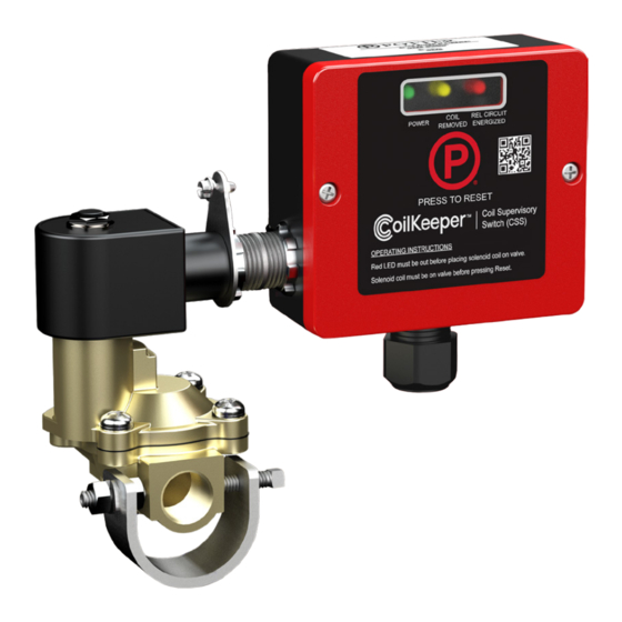
The CoilKeeper ™ Supervisory Switch (CSS) is designed to supervise
the position of a coil on a solenoid for a preaction/deluge system as
required by NFPA 13. The unit monitors the coil electronically and
determines if the coil is installed on the valve stem. If a technician
removes the coil from the stem the CoilKeeper will activate a normally
open set of dry contacts that can be wired to a supervisory circuit of the
releasing control panel.
Local LEDs at the CoilKeeper shows when the coil is in a normal state
on the valve body, when the coil is removed from the valve body in
a maintenance state, when the releasing circuit is energized and if the
coil is open or shorted. The releasing circuit energized LED allows the
technician to locally see the state of the circuit, preventing accidental
release by re-installing an energized coil.
•Installation must be performed by qualified personnel and in
accordance with all national and local codes and ordinances.
•Shock hazard. Disconnect power source before servicing. Serious
injury or death could result.
•Read all instructions carefully and understand them before starting
installation. Save instructions for future use. Failure to read and
understand instructions could result in improper operation of
device resulting in serious injury or death.
•Risk of explosion. Not for use in hazardous locations. Serious injury
or death could result.
Potter Electric Signal Company, LLC
Patents Pending
Technical Specifications
Specifications subject to change without notice.
•
St. Louis, MO
5401604 - REV D • 10/22
Solenoid Supervisory Switch Series
Conduit Entrances
Contact Ratings
Dimensions
Enclosure
Environmental Limitations
Power Requirements
Shipping Weight
Solenoid Valves
Wattage Range
Temperature Range
Wire Range
•
Phone: 800-325-3936
CoilKeeper
1/2" conduit connections provided (3
total)
1A at 30 VDC Resistive
4.38" W x 4.00" H x 1.90" D
UV and impact resistant
polycarbonate
NEMA type 2 for indoor dry use
24 VDC, 20 mA max standby, 40 mA
max alarm (20 mA AUX power, 20
mA releasing circuit)
1.25 lbs
For use with 24V solenoid valves UL
listed for releasing service
CSS-10: 9-11 Watts
CSS-25: 22-31 Watts
32° F to 120°F (0°C to 49°C)
12-22 AWG
•
www.pottersignal.com
PAGE 1 OF 6
™
Advertisement

Related Manuals for Potter CoilKeeper CSS


Summary of Contents for Potter CoilKeeper CSS
- Page 1 Specifications subject to change without notice. •Risk of explosion. Not for use in hazardous locations. Serious injury or death could result. Potter Electric Signal Company, LLC • St. Louis, MO • Phone: 800-325-3936 •...
-
Page 2: Remote Installation
Set Screw Install conduit from the junction box to the CoilKeeper Locknut Note: Maximum wire resistance 100 ohms U Bracket DETAIL A SCALE 1 : 1 Potter Electric Signal Company, LLC • St. Louis, MO • Phone: 800-325-3936 • www.pottersignal.com 5401604 - REV D •... - Page 3 Liquid tight cord grip Typical 1/2” solenoid valve, not included Sense return wire Sense return clamp Potter Electric Signal Company, LLC • St. Louis, MO • Phone: 800-325-3936 • www.pottersignal.com 5401604 - REV D • 10/22 PAGE 3 OF 6...
- Page 4 Wire ground to sense return terminal if required by NEC, local electric code or AHJ. Solenoid coil / valve assembly is grounded through the CoilKeeper sense return clamp. Potter Electric Signal Company, LLC • St. Louis, MO • Phone: 800-325-3936 •...
-
Page 5: Troubleshooting
Press the reset button on the CoilKeeper. Note: If CoilKeeper fails to reset a local error code will be flashed. Refer to troubleshooting for more information. Potter Electric Signal Company, LLC • St. Louis, MO • Phone: 800-325-3936 •... - Page 6 145.88 *Solenoid valve pictured is for illustration purposes only and is not DATA CONTAINED HEREIN SHALL NOT BE USED, DUPLICATED OR DISCLOSED IN WHOLE OR PART OUTSIDE POTTER ELECTRIC, INC. WITHOUT WRITTEN PERMISSION OF SAME. 4.38 included with the CoilKeeper.
Need help?
Do you have a question about the CoilKeeper CSS and is the answer not in the manual?
Questions and answers