Table of Contents
Advertisement
Quick Links
Specifications subject to change without notice.
Ordering Information
Nominal Pipe Size
Model
2"
DN50
VSR-AT-2
2 1/2"
DN65
VSR-AT-2 1/2
3"
DN80
VSR-AT-3
3 1/2"
-
VSR-AT-3 1/2
4"
DN100
VSR-AT-4
5"
-
VSR-AT-5
6"
DN150
VSR-AT-6
8"
DN200
VSR-AT-8
Optional Power Supply: Ordering Information
Model
-
Power Supply
BT-80
12V Battery-8AH (2 REQUIRED)
Optional Test Switch: Ordering Information
Model
ATC-1
Single Zone Test Control
ATC-4
Four Zone Test Control
SGB-R
Single Gang Box-Red
DGB-R
Double Gang Box-Red
General Information
The model VSR-AT is an electronic vane type waterflow switch for
use on wet sprinkler systems. It is UL Listed and FM Approved for
use on steel pipe schedules 10 thru 40 sizes 2" thru 8". See ordering
Information chart.
The VSR-AT may also be used as a sectional waterflow detector on large
systems. The VSR-AT has two sets of alarm contacts and an adjustable
instantly recycling electronic retard. The alarm contacts are actuated
when a flow of 10 GPM (38 LPM) or more occurs downstream of the
device. The flow condition must exist for a period of time necessary to
overcome the selected retard time.
The VSR-AT may be remotely tested without flowing water by using
the optional auto test Control model ATC-1or ATC-4 or the use of
addressable relays and monitor modules as part of a listed addressable
Potter Electric Signal Company, LLC • St. Louis, MO • Phone: 866-956-1211/Canada 888-882-1833 • www.pottersignal.com
Part #
Replacement PCB #
1116102
1029074
1116125
1029075
1116103
1029076
1116135
1029077
1116104
1029078
1116105
1029079
1116106
1029080
1116108
1029081
Description
Part Number
3006479
5130084
Description
Part Number
1000221
1000224
1000483
1000484
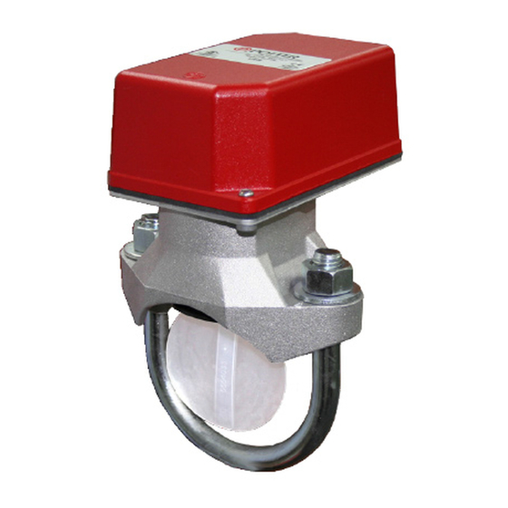
AUTO TEST VSR (VSR-AT)
VANE TYPE WATERFLOW ALARM SWITCH WITH
ELECTRONIC RETARD AND AUTO TEST FEATURE
UL, CUL, FM Approved
Service Pressure:
Flow Sensitivity Range for Signal:
Maximum Surge:
Contact Ratings:
Power Requirements: 24 VDC From Listed or Approved Source
Typical Current Draw:
Conduit Entrances: Two knockouts provided for 1/2" conduit.
Environmental Specifications:
• NEMA 4/IP54 Rated Enclosure suitable for indoor or
outdoor use with factory installed gasket and die-cast housing
when used with appropriate conduit fitting.
• Temperature Range: 40°F - 120°F, (4.5°C - 49°C) - UL
• Non-corrosive sleeve factory installed in saddle.
Service Use:
Automatic Sprinkler
One or two family dwelling
Residential occupancy up to four stories
National Fire Alarm Code
Important: This document contains important information on the
Installation and operation of VSR-AT waterflow switches. Please read
all instructions carefully before beginning installation. A copy of this
document is required by NFPA 72 to be maintained on site.
• Installation must be performed by qualified personnel and in
accordance with all national and local codes and ordinances.
• Shock hazard. Disconnect power source before servicing. Serious
injury or death could result.
• Risk of explosion. Not for use in hazardous locations. Serious
injury or death could result.
Waterflow switches that are monitoring wet pipe sprinkler systems shall
not be used as the sole initiating device to discharge AFFF, deluge,
or chemical suppression systems. Waterflow switches used for this
application may result in unintended discharges caused by surges,
trapped air, or short retard times.
fire alarm panel.
When the auto test feature is initiated, the VSR-AT performs a self test to
ensure compliance with UL requirements regarding waterflow detection
and retard time. In addition, the auto test feature ensures the integrity of
the paddle/trip stem assembly. A successful completion of the auto test
will activate both sets of normally open contacts on the flow switch. If
the auto test detects a problem with the trip stem/paddle assembly or if
there is no water in the pipe, neither normally open contact will operate
and the flow switch will indicate a trouble condition at the test switch
and transmit a trouble signal to the fire alarm panel.
Enclosure
The VSR-AT switches and retard device are enclosed in a general
purpose, die-cast housing. The cover is held in place with two tamper
resistant screws which require a special key for removal.
MFG. #5401239 - REV B
3/14
450 PSI (31 BAR) - UL
4-10 GPM (15-38 LPM) - UL
18 FPS (5.5 m/s)
2.5 AMP @ 125/250 VAC & 30 VDC
With Battery Backup
Standby 20 mA
Alarm 65 mA
Autotest 120 mA
NFPA-13
NFPA-13D
NFPA-13R
NFPA-72
PAGE 1 OF 6
Advertisement
Table of Contents

Related Manuals for Potter VSR-AT Series


Summary of Contents for Potter VSR-AT Series
- Page 1 Potter Electric Signal Company, LLC • St. Louis, MO • Phone: 866-956-1211/Canada 888-882-1833 • www.pottersignal.com PRINTED IN USA MFG. #5401239 - REV B...
- Page 2 If an alarm Potter PAV or similar to exhaust air out of the system and allow the piping to is not desired, a qualified technician should disable the alarm system.
- Page 3 AUTO TEST VSR (VSR-AT) VANE TYPE WATERFLOW ALARM SWITCH WITH ELECTRONIC RETARD AND AUTO TEST FEATURE Fig. 2 Fig. 3 Switch Terminal Connections Clamping Plate Terminal To remove knockouts: Place screwdriver at inside edge of knockouts, not in the center. An uninsulated section of a single conductor should not be looped around the DWG 1146-4 terminal and serve as two separate connections.
- Page 4 AUTO TEST VSR (VSR-AT) VANE TYPE WATERFLOW ALARM SWITCH WITH ELECTRONIC RETARD AND AUTO TEST FEATURE Fig. 6 Typical Electrical Connections Do not connect power directly to these terminals. Bell NO GND LED SWITCH Neutral Load 24 VDC PWR ALARM ALARM (White) (Black)
- Page 5 AUTO TEST VSR (VSR-AT) VANE TYPE WATERFLOW ALARM SWITCH WITH ELECTRONIC RETARD AND AUTO TEST FEATURE Fig. 7 Typical Electrical Connections For Operation by Addressable Fire Alarm Panel Do not connect power directly to these terminals. Bell NO GND LED SWITCH Load Neutral...
- Page 6 The NO and End of Line Resistor terminals are connected in- • For other issues contact Potter Tech Support at 866-956-1211 ternally by a normally energized relay. A loss of power or failed or visit our web site at http://www.pottersignal.com/ run your...
Need help?
Do you have a question about the VSR-AT Series and is the answer not in the manual?
Questions and answers