Table of Contents
Advertisement
Quick Links
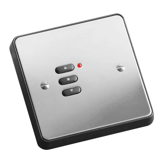
Three button Mounted Switch RPS03-** Installation, Programming and Operating Instructions.
The rako three button control panels are designed for use with the Rako
RACUB motor control units only with raise lower and stop functions.
Rako switches are designed to cope with a number of different
Installation situations.
These are predominantly:
Flush fixing into a UK back-box.
Surface mounting with a UK back-box
Surface mounting with no back-box or onto a European DIN standard or
French box.
In order to fit successfully into all the above situations the wall-plate is
made from an assembly of parts, all of which are supplied as standard and
are listed below. The parts can also be identified from the drawing Fig1.
(Note: Depending on the application not all of the parts may be used)
1 x Front plate.
1 x PCB retainer (complete with PCB
and button pad).
1 x Rear cover.
1 x Patress.
1 x Universal backing plate.
Universal
backing plate
Front Plate
Front View of Components
Batteries
Pull-out
Tab
Prise Point
Addressing
Switches
Fig 2. Rear View of PCB Retainer and Rear Cover
General
2 x 6mm M3.5 fixing screws.
2 x 25mm M3.5 fixing screws.
2 x self-tapping screws.
PCB Retainer
Fig 1.
This section must be read and followed before installation of the Rako
wall switch.
Rako wall mounted switches are supplied with a pullout tab to prevent
inadvertent operation and battery deterioration during transit. To remove
this and to access the address switches remove the rear cover.
Insert the tip of a small screwdriver or similar into the prise point (Fig. 2)
and gently lift off the rear cover. This should expose the battery
compartment and addressing switches. Care should be taken not to
touch or otherwise damage any of the exposed electronic components.
With the rear cover removed pull out the tab protecting the batteries (see
Fig.2); the Rako wall switch should now be operational. To check this
press one of the buttons on the front of the PCB retainer and the
indicating LED should illuminate briefly for a single flash. If the LED does
not flash or it flashes repeatedly for a short burst (low battery warning)
then you should contact your Rako dealer.
To avoid interference between adjacent rooms of a house and
neighbouring houses as well as allowing individual control of separate
curtains/blinds within a room rako radio controllers employ a structured
addressing system.
Rako radio systems use a structure based on house, room and channel
addresses. Using the two banks of DIL switches on the back of a wall
panel or hand control (see Fig.3) a House address can be selected from
one of up to 255 possible addresses and a Room address from one of up
to 255 possible addresses.
House 0 is not a valid address and Room 0 is a special address which
Patress
gives overall control for a whole house. Room 0 should not be selected
as a Room address without careful thought regarding the application.
Setting an address is the way in which interference between other Radio
Controlled Radio systems, either with other rooms within your house or
neighbouring houses, is avoided. It should be remembered that a Rako
transmitter may have a range of over 100m.
Rako controllers come set with a default address of House 1, Room 4,
Rear Cover
Channel 1 and whilst the unit will function with this address it is strongly
advised that a specific and logical address for both House and Room be
selected
Modules can be given channel addresses from 1-8 allowing control from
the 7 button wall-plates and hand-held controllers.
Some advanced grouping arrangements are possible allowing banks of
modules to be controlled as groups within a room. Systems with
advanced programming need to be factory set. For more details contact
Aerial Cutouts
Rako.
Each Rako transmitter has two, 8 way banks of switches for setting its
address. The two sets of switches allow the user to choose from 255
house addresses and 255 room addresses. To set the address, remove the
rear cover (refer to controller manual for details), whereupon the banks of
switches will be now become visible. To set an address, use a small
Page 1
Setting Up and Addressing the Units
Important
Rear cover removal.
Checking for correct operation
Set-up and Addressing
Note
Setting an Address
Advertisement
Table of Contents

Related Manuals for rako RPS03 Series


Summary of Contents for rako RPS03 Series
- Page 1 Three button Mounted Switch RPS03-** Installation, Programming and Operating Instructions. General Setting Up and Addressing the Units The rako three button control panels are designed for use with the Rako Important RACUB motor control units only with raise lower and stop functions.
- Page 2 Once a House and Room number have been selected on a control panel these need to be transmitted to each receiving module along with a valid channel number. This is done by one of two methods using a Rako wall switch , hand-held transmitter or Rako software RASOFT .
- Page 3 Care and maintenance Single Channel Transmitters Battery replacement The Rako series of wall-switches are designed to be powered by batteries. Single channel transmitters only allow simultaneous control of all The designed battery life is better than 3 years (based on 30 button channels in a room.
Need help?
Do you have a question about the RPS03 Series and is the answer not in the manual?
Questions and answers