Advertisement
Quick Links
C
RR Concepts
R R
S
tation aster -
Train Controller
This manual contains detailed hookup and programming instructions for the StationMaster-6 train
controller available in a 4 AMP or 10AMP configuration. The StationMaster-6 can perform station
stops and reversing operations. It can perform all the functions of the StationMaster-5 XL Full Featured
and also contains more advanced hardware and software features described online at StationMaster.net.
The StationMaster-6 can control DC trains or DCC trains set to linear mode.
Before we Start
transformer) to any other terminals except the designated input pins 1 and 2.
Your StationMaster will be damaged if power is put on any of the sensor terminals.
ONLY ATTACH WIRES WHILE THE POWER IS OFF.
Quick-connect terminals allow easy swap-out and removal of the electronics while leaving
the wires in place. The RR Concepts Magnet/Screwdriver tool is recommended for wire-up
and testing of operations.
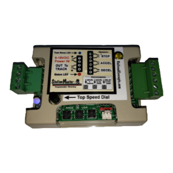
Train Sense LED
IN 8-24VDC
Out to Track
Status LED
Top Speed Adjust and
Programming Dial
External Relay Connector
for signal lights or external
device triggering.
M
- Please do not attach power wires (from your power pack or
See decal on bottom for optional programming information
4 AMP version shown
6
Programming
Pushbuttons
April 2023
Bypass Jumper
Sensor Inputs:
STOP
ACCEL
DECEL
"Justa-station-stop"
connector
Out to YardMaster data
cable connector.
1
Advertisement

Related Manuals for RR-Concepts StationMaster-6


Summary of Contents for RR-Concepts StationMaster-6
- Page 1 This manual contains detailed hookup and programming instructions for the StationMaster-6 train controller available in a 4 AMP or 10AMP configuration. The StationMaster-6 can perform station stops and reversing operations. It can perform all the functions of the StationMaster-5 XL Full Featured and also contains more advanced hardware and software features described online at StationMaster.net.
- Page 2 RR Concepts StationMaster CONNECTIONS and CONTROLS Bypass Jumper Train Detected LED IN 8-22VDC tation aster - Sensor Inputs: STOP Out to Track ACCEL Quick Hookup Instructions DECEL Sensor LED How to do Realistic Station Stops & Top Speed Adjust and “Out to YardMaster”...
- Page 3 RR Concepts Bypass and Manual Reverse Operation Sometimes automatic control is not desired so the StationMaster-6 contains a bypass feature. The SM-6 is shipped with a jumper installed on a 2 pin header, however a bypass switch could easily be installed with a cable that attaches to the header. When the contacts are”open”...
- Page 4 RR Concepts StationMaster Basic Hookup Description The StationMaster is designed to be installed between the train transformer, and the track. Attach terminals 1 & 2 to your transformer's DC output (Sometimes labeled as TRACK) or to a 12-22 volt power source. If using a train transformer set the throttle position to the desired top speed of the train.
- Page 5 RR Concepts ACCEL Sensor Terminals 10 and 11 are the optional Start Acceleration sensor inputs. When these terminals are shorted (sensor detects a magnet) the train will start to accelerate. This sensor is not necessary unless using “Block Control” or the time delay is set for maximum blinks.
- Page 6 RR Concepts StationMaster “Deadman Timer” A unique feature of the StationMaster is the DeadmanTimer. If a train is sensed on the track and no sensor has been detected for 10 minutes, the StationMaster will SHUT DOWN and flash both the Blue train sensed LED and the GREEN status LED.
- Page 7 RR Concepts Top Speed and Programming Mode Dial The Top Speed dial provides 3 functions: 1: Adjust the top "cruising" speed of the train. 2: Reduce the “creeping speed” when running in Diode Reverse Mode. 3: Enter programming mode. Top speed adjustment “Full speed"...
-
Page 8: Led Indicators
RR Concepts LED indicators Blue Train Detected LED Red/Green/Blue STATUS LED Train Sense LED Green: train is running. Status LED Train Sense LED Fast alternating Red/Green Flashing: train is CREEPING and hunting for Status LED the STOP sensor using the creep speed. 1. -
Page 9: Deceleration Rate
RR Concepts Programming: Deceleration Rate Fully counter clockwise 1. Make sure all three sensor inputs are open. 2. If the top speed dial is not already at zero, then turn the top speed dial to zero. (fully counter-clockwise.) The Blue “Train Detected” LED will “twinkle” 3. -
Page 10: Acceleration Rate
RR Concepts Programming: Acceleration Rate Fully counter clockwise 1. Make sure all three sensor inputs are open. (Red LED is off) 2. If the top speed dial is not already at zero, then turn the top speed dial to zero. (fully counter-clockwise.) BlueTrain Detected LED will “twinkle”. -
Page 11: Pause Time
RR Concepts Programming: Fully Pause Time counter clockwise 1. Make sure all three sensor inputs are open. (red Led is off) 2. If the top speed dial is not already at zero, then turn the top speed dial to zero. BlueTrain Detected LED will “twinkle”... -
Page 12: Operating Modes
RR Concepts Please go to RRconcepts.com to view an informational video on how to program Programming: operating modes. BLUE Operating Modes HOW TO PROGRAM: (Perform a factory reset to clear everything) 1. Enter Secondary Programming mode: (Skip this step if already in secondary programming mode) * Turn the Top Speed dial fully counter-clockwise to enter programming mode (Skip this step if already in programming mode). - Page 13 RR Concepts Additional Information on Programming Modes. The hookup diagrams will identify which of these need to be set. blink 1 = Simple Reversing Mode This will allow reversing operations with a DECEL sensor placed at the ends wired in parallel. After reversing the very next DECEL sensor will be ignored.
- Page 14 RR Concepts Please go to RRconcepts.com to view an informational video on how to program Programming: operating modes. BLUE Aux Relay Control The external auxiliary relay can be programed to behave in four different manners. These include: * Station Stop mode where the relay will turn on while entering the station and stopped. * Direction mode where the relay will turn on or off depending on the train direction.
-
Page 15: Factory Reset
RR Concepts Programming: Factory Reset Fully counter clockwise To set the StationMaster back to factory defaults perform the following: 1: Enter programming mode by turning the top speed dial fully counter-clockwise 2. Press and hold both button #1 AND button #3 at the same time. 3 Turn the top speed dial fully clockwise to exit programming mode. - Page 16 RR Concepts Programming: MULTIPLE LAPS Blue 1. Turn the Top Speed dial fully counter-clockwise to enter programming mode (Skip this step if already in programming mode). 2. Slowly turn the Top Speed dial clockwise until the GREEN LED turns on. This indicates secondary programming mode.
- Page 17 RR Concepts Programming: Blue Train Count The train count is needed for 3 reasons: 1. Manage different creeping speeds for up to 5 trains. 2. Send proper signals to attached YardMasters to correctly fire turnouts. 3. Allow running in a block-control mode. (Must be set for 1 train) For example, a 3 track siding using 2 YardMasters wired in parallel would have a train count of 3, since 3 trains will be controlled.
- Page 18 RR Concepts “Justa Station Stop” Justa-Station-stop performs a decelerate/Pause/Accelerate sequence without triggering an attached YardMaster or reversing. When operating in an alternating trains hookup, additional stations stops can be done at different locations around the loop without affecting the parked train. Add a 3 pin plug into the bottom right 3 pin header and attach the sensor to pins 1 and 3.
- Page 19 RR Concepts No Sensor Reversing Hookup The StationMaster-6 can operate in a reversing back-and forth mode using either sensors to detect the train, or diodes on the ends without sensors. Diodes can be attached in any fashion, or LGB 10151 units could be use in place of diodes.
- Page 20 RR Concepts No-Sensor Diode Reversing Mode, Continued... OPERATIONS: The Reverser has a 2 step speed profile and accelerates/decelerates to these speeds. Speed #1 is the top speed of the train set by the transformer. Speed #2 is a “creeping” speed which allows the train to always reach the diode isolators on the ends.
- Page 21 RR Concepts Reversing Operations - No Sensors Continued... Notes Always start a run when inside the diodes on the ends before pressing button #3. The train must travel the full length of track for the recorded value to be correct. LED Indications This LED will: Turn BLUE when a train is sensed on the track.
- Page 22 RR Concepts Basic Hookup Diagram for Automatic Station Stops with Deceleration/Acceleration using train sensors. Place MAGNET on bottom of engine. Power Pack TRACK Terminals StationMaster To Left Rail Stopping Position Attach to TRACK DECEL sensor Swap wires to go opposite direction For a simple station stop, this is all you need to do! Factory settings will be a gradual acceleration, gradual deceleration and 10 second stop.
- Page 23 RR Concepts Your train can stop at many stations on the loop by adding DECEL Multiple Station Stops sensors in parallel. Power Pack TRACK Terminals StationMaster Attach to TRACK Every sensor that the train passes over will cause a declerate/pause/accelerate sequence.
- Page 24 RR Concepts Block Control For 1 or 2 Trains on 1 track with gradual Decelerations and Accelerations. Can be located at a remote location on the railroad Programming: * Train count: 1 Power Pack * Time delay: maximum TRACK StationMaster Terminals or full speed...
- Page 25 RR Concepts Block Control For 1, 2, or 3 Trains on 1 track with gradual Decelerations and Accelerations using StationMasters. Programming: * Train count: 1 Power Pack TRACK * Time delay: maximum StationMaster Terminals When ORANGE is displayed DECEL sensor the next DECEL sensor will be ignored.
- Page 26 6. Station stop can be located at a remote location on your railroad far from the transformer. 7. StationMaster-6 shown. A protection diode is recommended when a StationMaster-5 is used. 8. When the input voltage is reversed the StationMaster-6 will dis-engage and allow full manual control and the train will run backwards without stopping.
- Page 27 RR Concepts “Creep-Stop” Deceleration for Incredible Realism A unique and extremely realistic feature of the StationMaster is “Creep-Stop” Deceleration. By using both a DECEL sensor and a STOP sensor the StationMaster will provide a very realistic self-adjusting station stop. Programming your StationMaster to use “Creep-Stop” is very easy: 1.
- Page 28 RR Concepts Reversing Operations using Sensors When programming Mode blink 1 is set the StationMaster will go into sensor reversing mode. Sensors are placed near the ends to signal the StationMaster to begin the deceleration / pause / accelerate operation. Optional STOP sensors on the ends stop the train at an exact location.
- Page 29 RR Concepts In-Between Stops while Reversing When running in a back-and-forth reversing operation, in-between station stops are accomplished by placing one ACCEL sensor on the track. The StationMaster will perform the “Justa-Station-Stop” operation. StationMaster ACCEL sensor terminals Terminals 10 11 NOTES: 1.
- Page 30 RR Concepts Alternating Trains in Opposite Directions SPRING-RETURN TURNOUTS TRACK CONNECTIONS StationMaster Programmed for Simple Reverse mode, “Blink 1” Note band on diodes, Switch direction they are on opposite ends. if SM does not light up. Place MAGNET Left Rail on bottom of engines.
- Page 31 RR Concepts Alternating Trains in Opposite Directions SPRING-RETURN TURNOUTS SENSOR CONNECTIONS Program for Simple Reversing Mode StationMaster For additional station stops around the loop see“Justa-Station-Stop” in the StationMaster manual.
- Page 32 RR Concepts Alternating Trains in Opposite Directions More Details... ------------------------------------------------------------------------ Parts Required: StationMaster: Qty 1 4 AMP or 10AMP version. Turnouts: Qty 2 (Both spring return) Track Isolators: Qty 4 Magnets: Qty 2 (or one per train) Sensors: Qty 4 Diodes: Qty 2 Description...
- Page 33 RR Concepts Alternating Trains Powered Turnouts Two trains take turns with a time delay station stop. TRACK CONNECTIONS Right Rail should have NO isolators and will be connected straight thru StationMaster 3 pin data cable Switch direction if SM does not light up.
- Page 34 RR Concepts Alternating Trains Powered Turnouts SENSOR CONNECTIONS StationMaster DECEL sensor Stop sensors wired in parallel, one in each siding. No polarity. YardMaster 13 14 To Turnout Second turnout can be wired in parallel or floating. OPERATIONS * Two trains will take turns running on the loop using an optional lap count. When the train has stopped the next train will run after the time delay.
- Page 35 RR Concepts == Parts List == 1 StationMaster-6 1 YardMaster-5 2 Train sensors Station Stop with a Siding 1 magnet 1 three pin data cable After a few laps on the main line, go into the siding and stop. StationMaster...
- Page 36 RR Concepts Programming: BLUE Stopped Voltage When the train is stopped, a small voltage can be put on the track to mantain lights, smoke, or sound. This feature can be set from the tertiary (third) programming mode. Notice that a setting which is too high could cause the train to creep. Choose a setting which works for your train.
- Page 37 RR Concepts Automatic Shutdown Details The StationMaster has advanced electronics and software which will attempt to protect itself and also your trains when potentially disastrous events occur. Some transformers know their current capability and will shut down when a current threshold is reached but for sensitive electronics this is sometimes too late.
- Page 38 RR Concepts Electrical Details For reference only The locations of the common grounds could be useful for some wiring harnesses. tation aster + Voltage INPUT Common Ground Common Ground Sensor Input Common Ground Output Voltage to Track Sensor Input Output Voltage to Track Common Ground Sensor Input + 5V...
- Page 39 These smaller sensors can be used for N, HO, etc. Contact RR Concepts for these sensors. WARRANTY Your StationMaster is warranted, and guaranteed operational for 1 year. It will be repaired or replaced at no charge within that time period. Contact http://www.RR-Concepts.com for additional information.
Need help?
Do you have a question about the StationMaster-6 and is the answer not in the manual?
Questions and answers