Table of Contents
Advertisement
Advertisement
Table of Contents

Related Manuals for Gaspar XICOY X Series


Summary of Contents for Gaspar XICOY X Series
- Page 1 icoy TurboJet Engines User Manual Version 1.4/2022 Page 1...
- Page 2 Congratulations on your purchase of a new generation Xicoy “X” Series gas turbine engine. We are confident you will be pleased with your purchase and your new engine will give you excellent ser- vice and maximum enjoyment to your hobby. “X”...
-
Page 3: Table Of Contents
If you sell or pass on this engine to a 2 or subsequent owner please also pass on this User’s Manual or its link, so they can enjoy a safe and fulfilling ownership too. The Xicoy Electronica SL responsibility is limited exclusively to the repair of the engine and acces- sories which are outlined in the conditions of warranty. - Page 4 Auto Power-Off..........................19 Hub installed ambient sensors ....................19 Fuel Pump ............................20 Construction..........................20 Pre-setting............................. 21 ECU Display ............................22 ECU data record / playback ....................... 22 Plug-in backlit display........................23 Navigating Menu Screens ....................... 24 Engine Installation: Electrical connections .................. 29 Shared ECU battery ........................
-
Page 5: Legal And Disclaimer
Legal and Disclaimer The engine design and contents of this User Manual are copyright Xicoy Electronica SL, Canet de Mar, Barcelona, Spain. All rights are reserved. This User manual, pictures and data are the property of Xicoy Electronica SL and cannot be used or reproduced in any way with written permission from Xicoy Electronica SL. - Page 6 Simply slackening the compressor nut on the engine will lose the delicate balance condition of ro- tor without which the engine may not run without sustaining damage to the rotating assembly. This warranty is voided if any one or more of the following conditions applies. In such a case Xicoy Electronica SL will accept no responsibility for any damage or other consequence caused by engine operation.
-
Page 7: Safety Notes
Safety Notes Please remember that though this engine is small it is most definitely NOT a toy and has the po- tential to hurt you or others around you if misused. The engine is a very high performance ma- chine in miniature and must always be treated with a high level of care and safety when in your operation. -
Page 8: General Notes
General Notes This engine is a real gas turbine machine with very high rotational speeds and high temperature fast moving exhaust. Despite the small intake the engine is able to swallow a huge amount of air and anything else that air can carry with it. So before running please carefully check the area sur- rounding the front and back end of the engine for any loose materials like rags, sawdust, sand or grit, modelling materials, liquids, or anything else that can be picked up by the airstream and sucked into the engine, or blown out at speed by the exhaust. - Page 9 need priming like a petrol or glow engine to start, so when filling the fuel line for the first time leave a couple of cm of empty pipe where it connects to the engine to be sure you have not pushed a puddle of fuel into the engine which can cause a flame on start-up.
-
Page 10: Engine Specifications
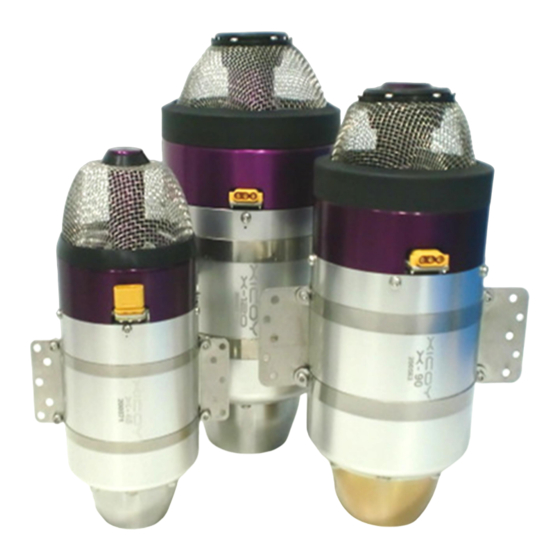
Engine Specifications X85/X90 X120 X180 Engine diameter 60mm / 2.35” 76mm / 3” 90mm / 3-1/2” 106mm / 4-1/8” Length 160mm / 6.3” 183mm / 7.2” 198mm / 7.8” 247mm / 9.8” Engine weight 398g / 14oz 706g / 1.6Lb 940g / 2.1Lb 1400g / 3.1Lb Total installed weight... -
Page 11: Package Contents
Package Contents Engine unit inc. fod screen Fuel pump Hub Lite + colour display + 300mm signal cable, OR / Compact Hub Engine cable 450mm Battery cable Servo type cable 300mm x 1 Fuel filter 4mm tubing, 1mtr (also 0,6mtr of 6mm fuel tube, X120 -X180 only) Instruction card USB ECU Battery The engines have been designed to use a Lipo battery for power and all factory tests on all en-... -
Page 12: Fuel
When the receiver is turned back on, the Hub unit will reconnect the battery. At the end of the flying day it is good practice to disconnect the ECU battery as safety measure because the ecu use a very small amount of current that can drain a 2000mAH battery in 1-2 month. Fuel The engines can be run using Kerosene or Diesel fuel. -
Page 13: Engine Description
Recommended commercial oil is Deluxe Power Model Jet Oil. Other commercial turbine oils like Kingtech oil, Fuchs… can be used. Don’t use Jetcat oil or Jackadofsky oil on the X45. These cause a lot of bearing drag when cold causing difficult or impossible start-up. - Page 14 The engine speed between idle and maximum is controlled by varying the speed of the fuel pump rotor by command from the electronic device called an ECU (Electronic Control Unit) that is mounted under the front cover of the engine. This sends commands to the fuel pump via a con- nector board (Hub) to turn at a certain rpm (and therefore flow rate) to deliver a precise amount of fuel and the fuel pump automatically adjusts itself to this rate.
- Page 15 The fuel pump should be located close to the fuel tank as convenient. Fit the inline filter between tank and pump to protect the pump from particles that could jam the pump. The pump has two screw fixings provided for mounting to the airframe. If using “Tygon”...
- Page 16 the greatest flight security. The engine can accommodate any slight changes due to the installa- tion. Don´t forget to blank off and cover the end of the fuel feed pipe to keep it clean. Page 16...
-
Page 17: Component Description
Component Description ECU (Engine Control Unit) The ECU and indeed the whole system used on these engines are totally new and unlike any pre- vious version of Xicoy ECU. It is a new controller developed specifically for this application by Xicoy Electronica which is in the form of a small C-shaped pcb fitted under the front cover of the engine. -
Page 18: Kero/Diesel Selector
Kero/Diesel Selector The kero/diesel option which switches between preset routines for each fuel. This saves you the ordeal of having to make many adjustments to fine tune the starting every time you switch fuels, now you just press a button to click your fuel, and go. Diesel being heavier and higher flashpoint fuel than kerosene requires a different start technique to enable it to start quickly and cleanly. -
Page 19: Auto Power-Off
ECU on the engine Any display used, either on-board as part of the connector board, or separately plugged in Additional input sensors such as pitot pressure, rpm from a 2 stage, etc. Additional output devices such as telemetry, SD memory storage, Bluetooth etc. Auto Power-Off The Hub has some intelligence of its own in that it can take a signal from the ECU and isolate (power down) the ECU battery after a cooldown has completed and the receiver turned off. -
Page 20: Fuel Pump
Telemetry connectivity possible using dedicated module. Xicoy website, www.xicoyturbines.com will show what is available for the “X” Series engines at any time, new items are being added regularly. Hubs have a printed panel showing where each cable goes and the orientation of each plug. For all cables, if you need a longer or shorter version than supplied, please contact Xicoy. -
Page 21: Pre-Setting
Please note, you must not try to run the pump by plugging this 3-wire cable into any brushless (3- phase) driver, the controller will be immediately destroyed. This system means the ECU does not have to spend time constantly controlling the pump speed, it only needs to send a brief signal to request a certain rpm. -
Page 22: Ecu Display
Priming It is strongly recommended that after a new installation or modification to the fuel system that the system be primed to clear any debris collected in the fuel line before connecting to the engine: engine does not (Note the itself require any priming) To prime the fuel system, disconnect the fuel pipe at the engine and route it into a suitable con-... -
Page 23: Plug-In Backlit Display
All the data, including all engine parameters, can also be saved later to a memory card, where it can be read using a text editor, or our viewer software. Also this data can be sent to Xicoy to be studied. Plug-in backlit display Display Screens available on the Plug-in backlit colour display: Initial Screen... -
Page 24: Navigating Menu Screens
Navigating Menu Screens The screen display is straight forward to navigate once you get the hang of it. We use the backlit display but the Compact Hub display is very similar, just follow the buttons. Start by plugging in the display to see the open screen. Note there are four buttons underneath the dials, <... - Page 25 Next is the setting for minimum pump speed during the start. Only adjust this if the combustion is slow to get going. 100 is the usual default and it increments at 25 a time with + and – buttons. Too high a setting will make flames at the starting. Leave it as factory set.
- Page 26 Total time counter. This screen shows the total runtime in hours of the engine since new. It also shows engine serial number and software version. Test starter screen. This screen is used to test the action of the starter by pressing the button under the “On”.
- Page 27 Test Fuel Valve. This test refers to the valve supplying the main fuel supply to the combustion chamber of the engine. The only test you can do is press the button beneath the “On” and you hear a click from the front of the engine, to signal all is ok. Is a rarely used function.
- Page 28 RUN Menu. This menu is used to access all adjustable settings used for when the engine is running. Full Power Screen. This shows the maximum power setting corresponding to full throttle to the engine in Newtons and Lbs (L). (X90 shown) You can use the buttons to derate the engine maximum power.
-
Page 29: Engine Installation: Electrical Connections
Engine Installation: Electrical connections The “X” Series engines are very simple to install but main thing to be very careful of is any cable or battery connector which is not standard or has been modified in some way, as this can risk re- verse connection of power supply which will easily destroy ECU and other components, so please be extra vigilant before using junkbox cables and/or adapters. -
Page 30: Radio Setup
ECU setup The ECU is contained on the engine. All the operating parameters relating to the starting and run- ning of the engine are contained in its memory. All communications with the outside world occurs through the cable connected to the external Hub unit. The signal from the user’s radio receiver throttle channel is used to initiate and control all functions relating to engine operation. -
Page 31: Aligning Transmitter With Ecu
ducing the “trim-down” function. Using a digital trim cause unstable idle, and delay in shutting off the engine in emergency. Check your radio manual for this before you start. Avoid using the digital trim if at all possible. Do not to use a spring loaded “Throttle Cut” switch as it will prevent the engine carrying out the cooldown function. -
Page 32: Failsafe
Failsafe Never fly with the failsafe set to “hold”. It is strongly recommended that you setup your ra- dio system with the correct failsafe settings. In many countries it is mandatory that the engine stops in 2 seconds in the case of a failure of the radio link. To program correctly the failsafe on your radio: 1) Adjust the travel of the throttle channel from -100% (stop position) to +100% (full power) 2) Adjust the ECU to your radio as described above. -
Page 33: During Start-Up - General
cient, then it will be ignited in the exhaust, causing a hot start (in extreme cases a big fireball) that surely will not hurt the engine, but can destroy the model. So: During start-up - general During the start-up listen to the engine sound to check for positive sound of ignition, check looking from the exhaust that the kero is burning, or check for an increase in exhaust temperature in the display. -
Page 34: Starting The Engine
repeating. Pushing fuel directly into the engine will cause an uncontrolled fire at next startup. Starting the engine Set the throttle stick down and the trim up (“Idle”). Confirm that the screen shows "Ready" i.e. Ready to start! In the case that the exhaust temperature is over 100º, the ECU will power the starter to cool down the engine. -
Page 35: Adjusting The Engine Maximum Power
Adjusting the engine maximum power. The engine comes from factory adjusted for its maximum thrust. But it is possible to reduce the maximum power if necessary. To do so, go to RUN menu and scroll the menus up to “Max RPM”. Using the + and –... - Page 36 Manual restart: User can normally shutdown the ECU through the transmitter (by lower- ing the stick and trim). The ECU will execute the normal shutdown and post run cooling cycle. Once the cooling is finished (temperature below 100ºC), the ECU will return to power-up state allowing the engine to be restarted through the normal procedure (Trim-up, cycle stick).
- Page 37 sustaining enough flight for the re-start to be completed. Some aircraft examples include: lightly loaded planes, gliders, or multi engine planes. It is highly advised that a shutdown simulation be done before selecting Auto-restart option in the ECU RADIO menu. Do it during a normal flight at a high altitude, then throttle down to idle then begin a 15sec count down.
-
Page 38: Restart Disclaimer
Restart Disclaimer There are no circumstances Xicoy Electronica SL or any of its Service Agents and employees will accept or be held responsible for any losses or damages the Auto Restart feature causes should the owner operator choose to enable this function. Throttle curves The ECU controls the RPM in linear way, i.e., at half stick position the engine turn at half of the rotor RPM range. - Page 39 normal use. However the user can modify these default settings to allow the engine to run opti- mally in different conditions. The usual acceleration setting are set to AUTO which gives the engine a good response but tries to minimise the risk of over-fuelling in a sudden acceleration. In AUTO mode, the ECU adjusts itself for optimum running at the current ambient conditions reported by the sensors built into the Hub, and in extreme cases it also raises the idle speed accordingly.
-
Page 40: Diagnoses
TrimLow: Indicates that the signal received from the transmitter corresponds to the low- ered trim, that is to say, engine OFF. Ready: Indicates that the engine is ready for starting, and that the transmitter signal cor- responds to IDLE. StickLo!: This indicates that the throttle stick is in a position above IDLE, the engine will not start with the stick in this position. -
Page 41: Diagnosis Messages
Diagnosis messages: UserOff: The engine has been shut down because it has received the shutdown command from the transmitter. FailSafe: The engine has been shut down because of loss of the control signal from the transmitter. After 0,5s of detecting a loss or invalid RC signal, the ECU sets engine power to idle, and if after another 1,5seconds a valid signal is still not received the engine is shut down.
Need help?
Do you have a question about the XICOY X Series and is the answer not in the manual?
Questions and answers