
Related Manuals for Gaspar Xicoy X45Helicopter


Summary of Contents for Gaspar Xicoy X45Helicopter
- Page 1 X45H X45TP X45Helicopter icoy X45TurboProp Two Stage Gas Turbine Engines User Manual Version 1.1 Aug / 2020...
-
Page 2: Table Of Contents
The X45Heli and X45TurboProp are a new extension of a very extensive research and development programme by Gaspar Espiell & Xicoy Electronica SL supported by the latest fluid dynamics and analysis software to bring you miniature gas turbine power units of unparalleled performance and versatility in amazingly small packages. - Page 3 Fuel..................................24 Oil..................................25 Engine Description..............................26 Engine.................................. 26 Stage................................26 Engine Control..............................27 Component Description............................27 ECU (Engine Control Unit)........................... 27 Connector board, the “Hub Lite” and “Compact Hub”..................28 Auto Power-Off..............................28 Ambient Sensors..............................28 Fuel Pump................................29 ECU Display................................30 Hub Lite data record / playback...........................
-
Page 4: Xicoy X45 Helicopter And X45 Turboprop, Two New Engines To Enjoy
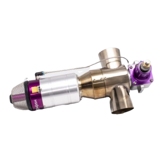
Xicoy X45 Helicopter and X45 Turboprop, two new engines to enjoy! Xicoy X45H, two stage miniature helicopter engine This new power unit from the Xicoy stable is a miniature 2stage gas turbine helicopter drive unit to power 0.90cu in (15cc) size pod and boom size R/C helicopters. The unit features a miniature gas turbine engine producing up to 3.5kw/4.7hp driving a 2 stage turbine linked to a gearbox just like standard full size practice. -
Page 5: Features And Functions
Features and Functions • Tiny 60mm case 2 stage engine developing up to 5kw of shaft power • Very low installed weight and bulk • Heli gearbox outline and shaft matches standard 90 size heli glow engine • Turboprop version comes complete with bulkhead mounting •... -
Page 6: Package Contents
Package Contents Helicopter engine: Engine unit inc fod screen Fuel pump Hub Lite + colour display + 300mm signal cable, OR / Compact Hub Engine cable 250mm Battery cable Servo type cable 300mm x 2 Aluminium filter 4mm tubing, 1mtr USB memory card with instruction manual TurboProp engine: Engine unit inc mounting and fod screen... -
Page 7: New Owners
New Owners If you sell or pass on this engine to a 2 or subsequent owner please also pass on this Users Manual or its link, so they can enjoy a safe and fulfilling ownership too. The Xicoy Electronica SL responsibility is limited exclusively to the repair of the engine and accessories which are outlined in the conditions of warranty. -
Page 8: Warranty
Warranty The warranty duration for this Xicoy X45H or X45TP engine is two years from date of completed purchase, or 25 running hours, whichever comes first. • Warranty is valid solely for the original 1 owner and is non-transferable upon resale. •... -
Page 9: Performance, Weights And Measures
Performance, weights and measures X45Heli X45 TurboProp Nominal power at sea level 3.5kw / 4.7hp 5kw/6.7hp Idle shaft rpm 4,000rpm 1200 (low 11.1:1 ratio) 1000 (high 13.5:1 ratio) Nominal max shaft rpm 20,000rpm (limited) 8krpm low ratio/6krpm high ratio Governor RPM range Rotor 800-2,400RPM Propeller RPM Limiter >4k RPM Torque at max rpm... -
Page 10: Installation - X45H Helicopter Engine
Installation – X45H Helicopter engine Please read through the section on Safety as there are many areas to consider that may differ from those pertaining to other forms of helicopter power plant. Helicopters have a special form of vibration due to assymetrical gyrations of the rotor head. -
Page 11: Exhaust Extensions
Exhaust extensions In normal operation, the engine exhaust flow is continually expanding as it leaves the 2nd stage. Adding extra exhaust ducting to the exhaust outlets inhibits the exhaust expansion and causes local restrictions to the free flow, increasing the back pressure on the engine. This reduces the power available to run the engine and has to be made up by burning more fuel. - Page 12 7. Fit a good quality silicon or ptfe (heat resistant) 3 wire type servo type cable from the small gearbox output pcb to connect to the auxiliary socket on the small Hub board. It may be difficult to do this later. Note orientation.
-
Page 13: Installation - X45Tp Turboprop Engine
Installation – X45TP TurboProp engine The engine unit is designed to operate horizontally with the engine markings upwards. A side and plan view can be downloaded from www.Xicoyturbines.com. Use the link to check for other sizes of mounting and views and propeller sizes to suit specific airframes as they become available. -
Page 14: Cooling
Cooling In operation the 2 stage radiates a lot of heat. The engine produces 100kw of heat per second, most goes straight out the exhaust after giving up energy to the propshaft but some is retained by the 2 stage parts, meaning it gets very hot in the immediate area inside the cowl at the front of the airframe. Allow plenty of propeller and forward flight airflow to be directed into the cowl area via openings and vents just as you would a petrol or glow engine and this will keep the area well ventilated and help prevent damage to surface finishes and/or paintwork. -
Page 15: Installing The Turboprop
Installing the TurboProp 1. Cut out holes for the exhaust, ideally positioned on any horizontal cowl split if there is one. Allow 6mm/1/4” clear all round. 2. Use M5 / no.10-32 nuts and bolts to fix the unit to the airframe, captive nuts are ideal. Do Not fix the engine unit in place with woodscrews, it is impossible to ensure they cannot loosen or pull through the firewall without warning. -
Page 16: Propeller Selection (Turboprop)
Propeller Selection (TurboProp) The Xicoy TurboProp unit is useable to power in a wide variety of aircraft. Being available in two ratios enables users to select the most appropriate for the intended application. The turboprop unit has been tested in a range of situations and loads. The main indicator of the performance of the unit from the users point of view, is the rpm that can be achieved with a given propeller load. - Page 17 The dynamic thrust (when the aircraft is in flight) will reduce as aircraft airspeed increases and is a function of all propeller driven aircraft. However, it is worth reminding that the thrust on an unrestricted turbo-prop falls off more gradually than an I/C engine due to the fact that as the propeller load reduces due to forward speed (“unloading”) the propeller rpm rises 10-20% to balance the torque supplied.
-
Page 18: Component Installation Notes - All Versions
Component Installation Notes – All versions Do NOT try to run the engine on its own. There is no need nor do we recommend attempting to run the engine outside of the airframe by way of functional test. With care, the turboprop can be run on a sturdy test stand with suitable propeller but there is no safe way to do so with the helicopter unit, and there is no need. - Page 19 The signal cable from the gearbox rpm sensor should be plugged in alongside the pump outlet with the same orientation. On the Compact Hub it is marked “Aux”. There is no specific marking on the Hub Lite but it should go below the pump outlet. If the ECU battery has to be sited at some distance perhaps in the tail for a heli, please contact Xicoy and ask for a longer cable in one piece.
- Page 20 The fuel pump should be located close to the fuel tank as convenient. The pump has two 3mm screw fixing holes provided for mounting to the airframe. Try not to mount the pump in close proximity to the front of the engine as being a brushless motor it might interfere with the rpm reading. If you want to fit a manual shutoff, fit a Festo 4mm type in the pressure side and locate it somewhere easy to see and get To prime the fuel system, disconnect the fuel pipe at the engine and route it into a suitable container.
- Page 21 We recommend test flying the engine in the airframe without bodyshell or cowl fitted for 1 test flights. Do not under any circumstances try to run the fuel pump by plugging it into any other FADEC brushless pump control or similar type 3-phase driver. It does not work like that and you will destroy it in the process.
-
Page 22: Safety Notes
Safety Notes Please remember that though this engine is small and compact it is most definitely NOT a toy and has the potential to hurt you or others around you if misused. The engine unit is a very high performance machine in miniature and must always be treated with a high level of care and safety when in your operation. -
Page 23: General Notes
• Always handle turbine fuel and oil with care as they are flammable and can cause a reaction with sensitive skin. Store them in clearly marked containers and always dispose appropriately. Use protective gloves when mixing and decanting fuel and oils. Avoid all skin, eye, mouth or ingestion contact with the liquids and ensure any spillage is wiped up immediately. -
Page 24: Ecu Battery
ECU Battery The engine has been designed to use a 2s Lipo battery for power and all factory tests on all engines are performed at a nominal 8v. 3S LiFe batteries are allowed in the case that 2s Lipo can’t be used, but if possible use 2s Lipo. Using a higher battery voltage than 10V will damage the ECU. -
Page 25: Oil
The engine requires oil for lubricating bearings and gears. This should be mixed at 4% with the fuel and all lubricating is then automatically metered and applied by the engine internal components. If you use a 20ltr fuel bottle then add 0.8l of oil. For every 3 gallons of fuel add 1 pint of oil. Some DTE oils work well in operation but leave very little slippery residue which can cause the bearings to sound dried out after cooling. -
Page 26: Engine Description
Engine Description Engine The heart of the engine is a miniature turbojet designed specifically to produce a gas flow to drive a 2 turbine to generate a shaft drive to power small model aircraft. It has a single stage billet machined centrifugal compressor and single stage cast Inconel axial flow turbine. -
Page 27: Engine Control
Engine Control The fuel for the engine is provided from a fuel tank and fed through a small pump driven by a 3-phase (brushless) motor that has its own intelligent control. The engine speed between idle and maximum is controlled by varying the speed of the fuel pump rotor by command from the electronic device called an ECU (Electronic Control Unit) that is mounted under the front cover of the engine. -
Page 28: Connector Board, The "Hub Lite" And "Compact Hub
The ECU is programmed specifically with the engine operating characteristics, start parameters, throttle curves and operating routines. Some of these are user settable like the radio setup and maximum power settings which are accessed or modified via a menu system on a display. The display can be the full colour backlit version (Hub “Lite”) which plugs into the Hub, or directly on the Compact Hub black and white display. -
Page 29: Fuel Pump
Hub location Site the Hub unit in a location away from direct exhaust or sunlight heating as otherwise its ambient sensors will tell the ECU it is a hot day and moderate settings appropriately. The Hub communicates via digital link to the ECU, there are no analogue signals used. The Hub has a printed panel showing where each cable goes and the orientation of each plug. -
Page 30: Ecu Display
This system means the ECU does not have to spend time constantly controlling the pump speed, it only needs to send a brief signal to request a certain rpm. The onboard controller then looks after how this command is carried out and confirms it back when this is achieved. This enables the ECU to do other things like updating telemetry or collecting data from sensors, while still controlling the engine operation. -
Page 31: Plug-In Backlit Display
Playback mode can be still, forward or reverse, speed x1, x 10 and x100 in both directions, so can be easy to view the engine operation or investigate any issue at the field without the need of a computer or any other type of reader. -
Page 32: Navigating Menu Screens
Navigating Menu Screens The screen display is straight-forward to navigate once you get the hang of it. We show the backlit display but the Compact Hub display is very similar, just follow the buttons. Start by plugging in the display to see the open screen. <... - Page 33 Next is the setting for minimum pump speed during the start. Only adjust this if the combustion is slow to get going. 125 is the default and it increments at 25 a time with + and – buttons. Too high a setting will make flames at the starting or cool the burner too much and stop it working.
- Page 34 Total time counter. This screen shows the total runtime in hours of the engine since last reset. It also shows engine serial number and software version. Test starter screen. This screen is used to test the action of the starter by pressing the button under the “On”.
- Page 35 Return now to the main navigation menu. Choose now the RADIO option. You have a choice now to enter the menu for setting up the transmitter, or proceeding to other options. The transmitter setup is show in the relevant section in detail, so now choose the “No”...
- Page 36 Idle Speed screen. This is preset at Auto, normally 60,000rpm, which allows the ECU to modify the setting in response to atmospheric conditions. In hot or conditions of high altitude or low air pressure the ECU will raise this value. You can see any change the ECU has made by checking this screen.
-
Page 37: New Menu Items
New Menu Items These items are new additions to the regular Xicoy menu structure: Kero / Diesel selector Pump min preset Max Power preset Gearbox reduction Governor setting Propeller overspeed limiter Kero/Diesel selector This option switches between preset start routines for Diesel and Kerosene fuels. This saves the ordeal of having to make adjustments to fine tune the starting every time you switch fuels, now you just press a button to click your fuel, and fly. - Page 38 Governor Function This applies to Heli engines only. The governor is a built in function enabled in software that when enabled, takes a signal from the output of the 2 stage gearbox and and uses this to control the engine power within a narrow range of output rpm and hence rotor speed.
-
Page 39: Propeller Overspeed Limiter
Propeller Overspeed Limiter This feature applies to Turboprop engines and is a preset used to set a top limit to the propeller rpm independent of power setting. If the preset limit is exceeded such as in a dive or with too small a propeller, throttle setting will be automatically reduced. -
Page 40: Shared Ecu Battery
Shared ECU battery With small and light installations there may be the temptation to dispense with the receiver battery and run the receiver using a regulator from the ECU battery. This is an absolute No-No, strongly discouraged and is surely an incident/accident waiting to happen sooner than later. -
Page 41: Ecu Setup
ECU Setup The ECU is contained on the engine. All the operating parameters relating to the starting and running of the engine are contained in its memory. All communications with the outside world occurs through the cable connected to the external Hub unit. The signal from the users radio receiver throttle channel is used to initiate and control all functions relating to engine operation. -
Page 42: Turboprop Radio Setup
Turboprop radio setup There are no special conditions needed for the turboprop as it uses the regular throttle stick in the normal way. Follow the graphic below. Pre-setting Radio to ECU Confirm you have connected the ECU signal input to the throttle channel on your receiver. Confirm you have connected the gearbox cable to the HUB and have a blue light which flashes on rotation of the gearbox shaft or prop. -
Page 43: Aligning Transmitter With Ecu
Aligning transmitter with ECU As the display does not photograph well we have reproduced the display readings as a green box. Turn on the transmitter and receiver. The opening screen should show as below. Follow the steps shown to set your radio: Press Press Info... -
Page 44: Failsafe
Failsafe Never fly with the failsafe set to “hold”. It is strongly recommended that you setup your radio system with the correct failsafe settings. In some countries is mandatory that the engine stops in 2 seconds in the case of a failure of the radio link. To program correctly the failsafe on your radio: 1) Adjust the travel of the throttle channel from -100% (stop position) to +100% (full power) 2) Adjust the ECU to your radio as described above. -
Page 45: Priming/Purging The Fuel System
Priming/purging the fuel system Fuel system needs purging of all air after initial installation and also to clear any small particles picked up during installation: 1. Disconnect the fuel feed to engine. 2. Place a small container, cloth rag etc that the fuel feed pipe to the engine can be pointed into. 3. -
Page 46: Starting The Engine
Starting the engine 1. Manually check the gearbox output shaft is free from restriction, ie turn the heli fan a small distance or rotate the prop to make sure both are free. After a shutdown and cooling the output shaft can stick slightly from the main with main housing cooling, this small turning normally unclicks it and runs free. -
Page 47: Turboprop Engine Running
Quick Test? If your intention was just to functional test the engine you can shut off now, lower the throttle to idle and lower the trim to off, or switch your Throttle Cut switch to “off” to turn off the engine. The engine should now go into cooldown mode. -
Page 48: Adjusting The Engine Maximum Power
Adjusting the engine maximum power The X45Heli and X45TP engine comes from factory adjusted for optimum power settings. It is possible to change the maximum power setting if needed. To do so, go to RUN menu and scroll the menus up to “Max RPM”... -
Page 49: What The Auto-Restart Function Does Do
What the auto-restart function does do It automatically tries to restart the engine quickly and restore the power setting that is being asked by the transmitter. To trigger this function, the ECU checks: • The radio signal is valid, no failsafe condition. •... -
Page 50: Restart Disclaimer
2. In case you see the plane begins to stall or an uncontrolled landing is most likely, IMMEDIATELY set the trim and stick to STOP position to abort the restart function. A crash with the engine running normally ends with a fireball; a crash with the engine off is not likely to catch fire. -
Page 51: Throttle Curves (Turboprop)
Throttle curves (TurboProp) The ECU controls the RPM in linear way, i.e., at half stick position the engine produces power at half of the RPM range. However, jet engines develop shaft power in exponential way, meaning half RPM means approximately ¼ of shaft power. On small engines with a high idle to full power rpm ratio, or in a high drag/low power planes, often only the last 1/3 of the throttle stick produce significant power, with the low half stick travel being not much used. -
Page 52: Ecu Message Codes
Leave the acceleration and deceleration in Auto mode when using the engine with kerosene and at ambient temperatures below 25ºC and elevation below 500m. If diesel fuel is used, or ambient temperature is over 25ºC or altitude is over 500m, then the engine could experiment difficulties in accelerating. -
Page 53: Diagnoses
Low RPM: Engine had been shutdown because the speed has fallen below the minimum. Usually lack of fuel (bubble) HighTemp: Excessive temperature Battery!: battery voltage out of limits, or not connected. Pump Overload: There is a restriction in the fuel path from the pump to the engine, or in the engine itself.
Need help?
Do you have a question about the Xicoy X45Helicopter and is the answer not in the manual?
Questions and answers