Advertisement
Quick Links
Instruction Manual
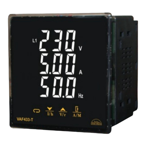
VAF433-T / VAF433-K
Introduction
The VAF is a panel mounted 96 x 96mm Digital Panel Meter
for the measurement of important electrical parameters like
AC Voltage, AC Current, RPM, Frequency and Power Factor
VAF can be configured and Programmed On site for the
following:
PT Primary, PT Secondary, CT Primary, CT Secondary (5A
or 1A) and System Type 3 phase 3W or 4W or single-phase
system.
The front panel has Four keys using which the user can scroll
through different screens and configure the product.
Introduction
WIRING: The probe and its corresponding wires should
never be installed in a conduit next to control or power supply
lines. The electrical wiring should be done as shown in the
diagram. The power supply circuit should be connected to a
protection switch. The terminals admit wires of upto 2.5sq
mm.
WARNING: Improper wiring may cause irreparable damage
and personal injury. Kindly ensure that wiring is done by
qualified personnel only.
Maintenance: Cleaning: Clean the surface of the controller
with a soft moist cloth. Do not use abrasive detergents, petrol,
alcohol or solvents.
Notice: The information in this document is subject to change
in order to improve reliability, design or function without prior
notice and does not represent a commitment on the part of
the company. In no event will the company be liable for direct,
indirect, special, incidental or consequential damage arising
out of the use or inability to use the product or documentation,
even if advised of the possibility of such damages. No part of
this manual may be reproduced or transmitted in any form or
by any means without the prior written permission of the
company.
Controller: Controller should be installed in a place
protected by vibration, water and corrosive gasses and where
ambient temperature does not exceed the values specified in
the technical data.
Probe: To give a correct reading, the probe must be installed
in a place protected from thermal influences, which may
affect the temperature to be controlled.
Dimensions & Panel Cutout
Connection Diagram
Index
Sr.
Parameter
Description
No.
Technical Specification.
User Interface.
Home Page Screen Description
1
Parameter setting mode.
2
Network selection 3P-4W, 3P-3W&1P-2W.
3
Select CT primary ratio.
4
Select PT primary ratio.
5
Select PT secondary ratio.
6
Select number of poles.
7
Clear run hours.
8
Restore factory defaults
Error Messages
Technical Specification
Housing
: Front Cover: Polycarbonate Plastic
Back Cover: ABS Plastic
Dimensions
: Frontal: 96 X 96mm, Depth: 61mm
Panel Cutout
: 92 X 92mm
Mounting
: Flush panel mounting with Fasteners
Protection
: IP65 Front
Connections
: Terminal connectors.
< 2.5sq mm terminal only with
U-type lugs.
Display
: 3 X 17mm 7 segment WHITE display,
15 Iconic LEDs for Indication
3 X 17mm 7 segment RED display,
8 Iconic LEDs for Indication
Data storage
: Non-volatile flash memory
Operating temp.
: 0°C to 60°C (non-condensing)
Operating humidity : 20% to 85% (non-condensing)
Storage temp.
: -25°C to 60°C (non-condensing)
Supply Voltage
: 230 Vac ± 10% , 50/60Hz Standard.
Wiring Input
: 3ø-4W, 3ø-3W system.
Measuring Range
Input Rated Voltage
: 11 to 375 V AC (L-N)
: 19 to 649 V AC (L-L)
Input Rated Current
: Nominal 5A AC
CT Primary
: 5 A to 10 kA
CT Secondary
: 5 A
PT Primary
: 100 V to 500 kV
PT Secondary
: 100 to 375 V AC (L-L)
Electrical Connection
: 3ø-4W, 3ø-3W, 2ø-3W, 1ø-2W.
Resolution
Current / Voltage
: Resolution depends upon CT,
PT Primary settings
RPM
: 0.1
Run Hour
: 0.1 Hr
Accuracy
Voltage
: ± 0.5% of F.S. ± 2 digits.
Current & Average Current : ± 1% of F.S. ± 2 digits
Frequency
: ± 0.1 Hz ± 1 digit
Run Hour
: ± 1%
RPM
: ± 0.5%
Display Scrolling
: Automatic or Manual
(Programmable)
Power Consumption
: 1.5VA Max
RPM
: 1350 to 1950
Pole: 0
(Range: 0-98, selectable in
steps of 2)
Frequency
: 40-70 Hz
Run Hours
: 0 to 99999.9 Hrs
Burden
: 0.5VA @5A per phase
User Interface
Sr.
Description
No.
Electrical parameters like AC Voltage, AC Current,
1
RPM, Frequency and Power Factor will be seen as
2
Per screen no and auto or manual mode. Kindly refer
3
Home Page Descriptor.
4
Unit Kilo Volts
5
Unit Volts (Only for T model)
6
Kilo Ampere
7
Ampere
8
Unit for Run Hours
9
Frequency units Hertz
Line to Line value of corresponding
10
Parameter (only for T model)
11
Line to Neutral value of First Phase
12
Average value of corresponding parameter
13
Line to Neutral value of Second Phase
14
Line to Neutral value of Third Phase
15
Line to line voltage
16
Line to neutral voltage
17
Next key:
In Manual Mode: To scroll for Next Screen.
In Program Mode: To scroll to Next
Parameter.
Note: Kindly refer 'Home Page Screen
Description' for further details.
18
Down key/ I/ h:
I h
In Normal Mode (Auto/Manual):
Press this key for 1 second, the First Screen
Displays phase current of three phases. Line
to neutral and line to line voltage of three
phases are displayed one by one.
Press this key for 3 seconds, to display
Run Hours (for non-zero poles).
In Program Mode: To increase Parameter
value.
Note: To return back to current page, press
for 3 seconds.
19
Up key:
V r
In Normal Mode (Auto/Manual):
Press this key for 1 second.
The First Screen displays line to neutral
voltage of three phases.
The Second Screen displays line to line
voltage of three phases.
Press this key for 3 seconds.
Displays rpm for non-zero poles.
In Program Mode: To increase Parameter
value.
Note: To return back to current page, press
for 3 seconds.
20
Exit key:
In Normal Mode:
A M
Press this key for 4 seconds to toggle
between Automatic/Manual Mode.
In Program Mode:
To save the changed Parameter and exit to
Normal mode.
Home Page Screen Description
Automatic Mode / Manual Mode Settings:
Press A/M mode for 4 seconds to toggle between
Automatic/Manual Mode.
Note: By Default, unit operates in automatic mode. In
automatic mode online pages scroll automatically at the rate
of 5 sec per page. In automatic mode if any key is pressed,
unit temporarily switched to manual mode and the
appropriate page is displayed.
In Automatic Mode:
1. Display Descriptions in 3Ø – 4W:
1
Screen
st
Displays Line to Neutral voltage of all 3 Phase
2
Screen
nd
Displays Line to Line voltage of all 3 Phase
3
Screen
RPM
rd
4
th
Screen
Displays current of all 3 Phase
5
th
Screen
Displays Run Hours
Displays Line to Neutral voltage, current of first
6
Screen
th
Phase
Displays line to neutral voltage, current of
7
th
Screen
second Phase
Displays line to neutral voltage, current of third
8
th
Screen
Phase
Displays average line to neutral voltage,
9
th
Screen
average current of three phase and frequency.
Displays average line to line voltage, average
10
Screen
th
current of three phases and frequency of
present phase.
2. Display Descriptions in 3Ø – 3W:
1
st
Screen
Displays Line to line voltage of all 3 Phase
2
nd
Screen RPM
3
rd
Screen
Displays Line to line current of all 3 Phase
4
th
Screen
Displays run hours
Displays Line to line voltage, current and
5
th
Screen
frequency of first and second Phase
Displays line to line voltage, current and
6
th
Screen
frequency of second and third Phase
Displays line to line voltage, current and
7
th
Screen
frequency of third and first Phase
Displays average line to line voltage, average
8
Screen
th
current of three phase and frequency
3. Display Descriptions in 1Ø – 2W:
Displays line to neutral voltage, current of
1
st
Screen
phase and frequency.
2
nd
Screen Displays Run Hours
3
rd
Screen
RPM
In Manual Mode:
To scroll through next screen press
1.Display Descriptions in 3Ø – 4W:
1
st
Screen
Displays Line to Neutral voltage of all 3 Phase
2
nd
Screen
Displays Line to Line voltage of all 3 Phase
3
rd
Screen
RPM
4
th
Screen
Displays current of all 3 Phase
key.
Advertisement

Related Manuals for Sub-Zero VAF433-T


Summary of Contents for Sub-Zero VAF433-T
- Page 1 Down key/ I/ h: Instruction Manual In Normal Mode (Auto/Manual): Housing : Front Cover: Polycarbonate Plastic VAF433-T / VAF433-K Press this key for 1 second, the First Screen Back Cover: ABS Plastic Displays phase current of three phases. Line Dimensions...
- Page 2 Error Messages 1 Phase - 2 Wire Screen Displays Run Hours 1 ø- 2 Wire, 1 CT's Message Description Displays Line to Neutral voltage, current of Screen first Phase It indicates corresponding parameter reach Displays line to neutral voltage, current of above specified measuring range.
Need help?
Do you have a question about the VAF433-T and is the answer not in the manual?
Questions and answers