Table of Contents
Advertisement
Quick Links
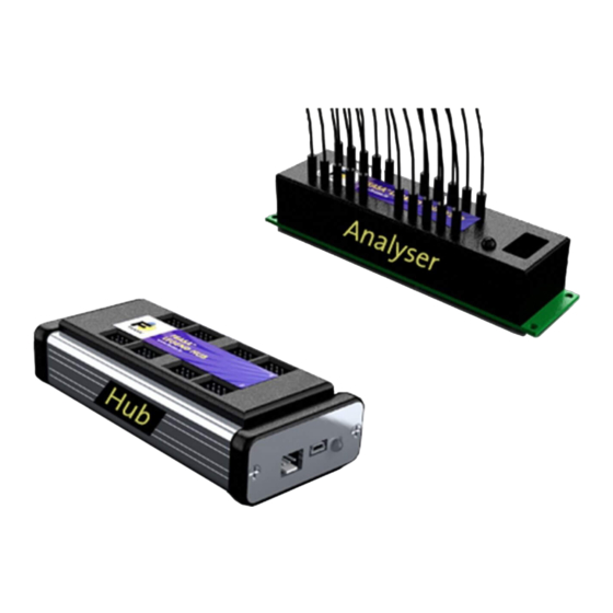
Feasa Legend LED Analyser
User Manual for Hub and Satellite
Satellite
Satellite
Satellite
HUB
Satellite
Satellite
Satellite
Satellite
Satellite
Feasa Enterprises Ltd,
Holland Road,
National Technology Park,
Castletroy,
Limerick,
Ireland.
www.feasa.ie
Email:
sales@feasa.ie
Rev. 1.20
Date: Dec, 2019
© Copyright Feasa Enterprises Ltd
1
Advertisement
Table of Contents

Related Manuals for Feasa Legend


Summary of Contents for Feasa Legend
- Page 1 Feasa Legend LED Analyser User Manual for Hub and Satellite Satellite Satellite Satellite Satellite Satellite Satellite Satellite Satellite Feasa Enterprises Ltd, Holland Road, National Technology Park, Castletroy, Limerick, Ireland. www.feasa.ie Email: sales@feasa.ie Rev. 1.20 Date: Dec, 2019 © Copyright Feasa Enterprises Ltd...
- Page 2 Feasa operates a policy of continuous development. Feasa reserves the right to make changes and improvements to any of the products described in this document without prior notice. Feasa reserves the right to revise this document or withdraw it at any time without prior notice.
-
Page 3: Table Of Contents
Feasa Legend LED Analyser Table of Contents Introduction............................5 Colour and Saturation...........................6 Intensity..............................8 White LED's............................10 Setting Tolerance Limits for Colour and Intensity................11 Product Description..........................12 Hub and Satellite Block Diagram....................13 Mode of Operation.........................14 Hub Controller Module........................15 External Input Port..........................16 External Input Logic Levels:......................17... - Page 4 Feasa Legend LED Analyser getuvall - Return the u'v' Chromaticity values................55 getIntensity### - Get the Intensity....................56 getIntensityall - Get the Intensity....................57 getIntGain###- Get the Intensity Gain Factor................58 getfactor - Get the exposure Factor...................59 General Set Commands........................60 SetIntGain - Set the Intensity GainFactor.................61...
-
Page 5: Introduction
Feasa Legend LED Analyser Introduction The Feasa Legend system is an instrument that tests the HSI (Hue, Saturation, Intensity), RGB (Red, Green, Blue Colour content of a single LED), xy Chromaticity, Dominant Wavelength and cct Colour temperature of Light Emitting Diodes (LEDs) in a test process. An individual Satellite can have up to 20* flexible Fiber-Optic Light Guides which are mounted individually over the LEDs to be tested. -
Page 6: Colour And Saturation
Blue, Green, etc. It is a relative output much the same as the Relative Intensity output, and is used to compare similarly coloured LEDs under test. The Saturation values are calculated within the Feasa Legend system for each channel of the Satellite Analyser, relative to the LED under test. - Page 7 Feasa Legend LED Analyser The RGB and Hue values in Figure 2 show how different Colour LEDs can be identified. SATURATION 100% Green Blue Yellow Orange White See Page 13 Figure 2. The RGB or Hue values are used to identify different Colour LEDs.
-
Page 8: Intensity
Is an Optical Head being used. There are 6 capture ranges each with an intensity output range of 0 to 99,999. Feasa recommends that the UUT readings should be in the 55K to 85K range for the best stability. - Page 9 Feasa Legend LED Analyser Figure 3b. Intensity for the LED Analyser in LINEAR Mode Back to Index © Copyright Feasa Enterprises Ltd...
-
Page 10: White Led's
Feasa Legend LED Analyser White LED's White LED's must be treated differently to coloured LED's when being tested. White is not a colour – it is a mix of all other colours. The three Primary colours Red, Green and Blue will be mixed in approximately equal proportions to display a White colour. -
Page 11: Setting Tolerance Limits For Colour And Intensity
C3, C4 or C5 would be recommended Figure 6. Note:- the Relative Intensity Value will depend on the Range selected. Note:- Feasa recommends selecting a Capture Range to achieve Relative Intensity Reading of 55K to 85K for the best results. Back to Index... -
Page 12: Product Description
Each Hub Controller can control up to 8 LED Analyser Modules and can test up to 160 LED's. All tests are executed at the same time. The Feasa Legend provides of an external port which allows to perform simple PASS/FAIL functional tests from external In-circuit Test machines, PLC controllers, micro-controllers or any other kind of test computer with I/O capabilities. -
Page 13: Hub And Satellite Block Diagram
Feasa Legend LED Analyser Hub and Satellite Block Diagram The function of the Hub is to control up to 8 Satellite LED Analyser Modules on the Test Fixture and to present a single Interface to the User Test System. The Hub can be controlled by a PC through the USB or Serial Interfaces. -
Page 14: Mode Of Operation
Feasa Legend LED Analyser Mode of Operation All the Satellite Analysers connected to the Hub are grouped together into one large virtual Analyser. The Fiber channels of each Analyser are added together to give one large Analyser. For example, if a 20 Channel and a 10 Channel Analyser are connected to the Hub then these Analysers will behave as if there is one 30 Channel Analyser. -
Page 15: Hub Controller Module
Feasa Legend LED Analyser Hub Controller Module The layout of the Hub Controller module is shown in Figure 8. Ports 1 to 8 are 6-pin connectors so that a flat 6-way ribbon cable can be used to connect to each Satellite LED Analyser module. -
Page 16: External Input Port
Feasa Legend LED Analyser External Input Port Name Pin type Function Description DATA0 Input Limit group (MSB) 4-bit binary code to select a Limit Group DATA1 Input Limit group DATA2 Input Limit group DATA3 Input Limit group (LSB) TRIGGER Input Test Trigger Input to start Automated Test cycle. -
Page 17: External Input Logic Levels
Feasa Legend LED Analyser External Input Logic Levels: Minimum input voltage: 0.0V Maximum input voltage: 5V Minimum otuput voltage: 0.0V Maximum otuput voltage: 3.3V Maximum output current per pin: 10mA < 0.8V ≥ 2.0V ≤ 0.6V ≥ 2.2V Important: - ensure that GND is properly connected and its voltage is actually 0V. - Page 18 Feasa Legend LED Analyser External Input Port BUSY Data0 Data1 Data2 PASS Data3 Trigger FAIL Reset Figure 10. Figure 10 illustrates how the External Input Port may be used. The Four Data lines are used to set the Limit Group to be used for the test.
-
Page 19: Functional Description
Feasa Legend LED Analyser Functional description Limit group A limit group is a set of values that define the low and high tolerable limits for a value under test. For example, when testing Intensity, we can set a lower limit of 65000 and an upper limit of 70000, so an Intensity value of 68000 will PASS, but a value of 75000 or 52344 will FAIL. -
Page 20: Test
PASS line (pin 7). The behaviour of these lines can be configured through the “Feasa ICTconfig” program. The Legend hub provides of a highly configurable Test, since the user can decide what kind of data will be given in the PASS/FAIL line: simple PASS/FAIL results through a HIGH/LOW status respectively •... - Page 21 Feasa Legend LED Analyser Diagram 1: Capture sequence with PASS result Note: it is recommended to wait for at least 20us before testing the PASS line. ≥ 20us → Capture Time. Depends on the capture range selected. Diagram 2: Capture sequence with FAIL result In case that any error occur, both PASS and FAIL lines will go to HIGH.
- Page 22 Feasa Legend LED Analyser Diagram 3: Capture sequence with ERROR result Set-up: Despite the format for the output data logged can be easily configured through the ICTconfig program, this type of error report output can be configured using the following serial...
- Page 23 Feasa Legend LED Analyser Diagram 4: Capture sequence with FAIL result + error ouput ≥ 20µs 10µs ≤ T0 ≤ 999µs (user configurable) 10µs ≤ T1 ≤ 999µs (user configurable) 10µs ≤ T2 ≤ 999µs (user configurable) For example, if fiber 3 and fiber 12 are failing, three bytes will be transmitted in total: the first for the number of errors (2), the second containing the number of the first fiber failing (3) and the third one containing the number of the seconds fiber failing (12).
- Page 24 Feasa Legend LED Analyser 1. Capture/trigger 2. FAIL status 3. Number of errors (8 bit) 4. Fiber number + flags for data type failing + flags for hi/lo status (3 bytes) for 1 error 5. Fiber number + flags for data type failing + flags for hi/lo status (3 bytes) for 2 error 6.
- Page 25 Feasa Legend LED Analyser START STOP Table 2: Data received: n. of errors (blue), data for 1st err (yellow); data for 2nd ( Set-up: Despite the format for the output data logged can be easily configured through the ICTconfig program, this type of error report output can be configured using the following serial...
- Page 26 Feasa Legend LED Analyser Diagram 6: Capture sequence with FAIL result + error ouput ≥ 20µs 100µs ≤ T < T ≥ 20µs ≥ 65ms (Timeout) Clocking for data retrieval should start in an interval higher than 100µs and lower than T...
- Page 27 Feasa Legend LED Analyser Capture + failing fibers + limits output (Synchronous) This is another extension for the previous case, in which additional information is provided for what limits are failing and whether it is failing the upper or the lower one.
- Page 28 Feasa Legend LED Analyser Table 3: Fail flags byte format The flag bit for Hue is the LSB, while the flag bit for Wavelength is the MSB. For example, if fiber 3 (Hue too low and x too high) and fiber 12 (Intensity too high) are failing, seven...
- Page 29 Feasa Legend LED Analyser Handling clocking errors (Synchronous) In case that the clock signal has been inactive for a period equal or greater than a T time, then a timeout is triggered and communication will be aborted. Diagram 8: clock interrupted before the data transmission ends ≥...
-
Page 30: Usb Port Control
Feasa Legend LED Analyser USB Port Control Connect the Hub to the PC using the supplied USB cable. USB Power is supplied through the USB Cable. The installed Software Driver will configure the USB Port automatically. The USB Port is configured as a Virtual Com Port and will be designated a name such as COM5, COM6, etc. -
Page 31: Led Analyser Module (Satellite)
Feasa Legend LED Analyser LED Analyser Module (Satellite) Physical Layout Conn Fiber Block 29mm 120mm Figure 12. Figure 12 shows the physical layout of the Analyser. The fibers are labeled 1-20. There are four 3mm diameter Mounting holes at the corners. -
Page 32: Capture Commands
Analyser. This program is also available as a drop down box in the User program and the Test Software program. The Feasa Limits Program is a graphical tool that can be used to send commands and receive results from the Analyser. It allows one LED to be tested at a time. -
Page 33: Auto Capture - Store Led Data
Feasa Legend LED Analyser Capture Mode AUTO CAPTURE - Store LED Data Transmit Receive Capture Description This Auto Range Capture command instructs all LED Analysers connected to the Hub to capture and store the Colour and Intensity of all the LED's positioned under the fibers. -
Page 34: Manual Capture - Store Led Data For A Specific Range
There are 5 manual capture ranges each with an intensity output range of 0 to 99,999. Feasa recommends that the UUT readings should be in the 55K to 85K range for the best stability. Back to Index... -
Page 35: Get Data Commands
Feasa Legend LED Analyser Get Data Commands The get data commands are used to read out the Colour, Saturation and Intensity data stored by the capture commands. The data from the last capture command remains in memory until a new capture command is issued or the power is removed from the Analysers. -
Page 36: Getrgbi### - Get Rgb And Intensity For A Led
Feasa Legend LED Analyser Get Data Mode getRGBI### - Get RGB and Intensity for a LED Transmit Receive getrgbi### iiiii Where: ### represents the Fiber Number in the range 001 – 160. are the red, green blue components of the LED color. -
Page 37: Getrgbiall - Get Rgb And Intensity For All Leds
Feasa Legend LED Analyser Get Data Mode getRGBIall - Get RGB and Intensity for all LEDs Transmit Receive getRGBIall iiiii Where: FFF represents the Fiber Number in the range 001-160 are the red, green blue components of the LED color. -
Page 38: Gethsi### - Get Hue, Saturation And Intensity
Feasa Legend LED Analyser Get Data Mode getHSI### - Get Hue, Saturation and Intensity Transmit Receive getHSI### hhh.hh sss iiiii Where: ### represents the Fiber Number in the range 001 – 160. hhh.hh represents the Hue (color) and is a number in the range 0.00 – 360.00. -
Page 39: Gethsiall - Get Hue, Saturation And Intensity
Feasa Legend LED Analyser Get Data Mode getHSIall - Get Hue, Saturation and Intensity Transmit Receive getHSIall FFF hhh.hh sss iiiii (multiple) Where: FFF represents the Fiber Number in the range 001 – 160. hhh.hh represents the Hue (color) and is a number in the range 0.00 – 360.00. -
Page 40: Getwavelength### - Get The Dominant Wavelength
Feasa Legend LED Analyser Get Data Mode getWAVELENGTH### - Get the Dominant Wavelength Transmit Receive getwavelength### Where: represents the Fiber Number and is a number in the range 001 – 160. represents the dominant wavelength of the LED in nanometers. -
Page 41: Getwavelengthall - Get The Dominant Wavelength
Feasa Legend LED Analyser Get Data Mode getWavelengthall - Get the Dominant Wavelength Transmit Receive getwavelengthall FFF www Where: represents the Fiber Number in the range 001 – 160. represents the dominant wavelength of the LED in nanometers. Description This command is used to get the Dominant Wavelength and Intensity data for all Fibers. -
Page 42: Getwavelengthoffset@@ - Get The Wavelength Offset
Feasa Legend LED Analyser Get Data Mode getWAVELENGTHOFFSET@@ - Get the Wavelength Offset Transmit Receive getwavelengthoffset@@ +/-XX Where: represents the Fiber Number and is a number in the range 1 – 20. +/- xx represents the wavelength offset set of the LED in nanometers. -
Page 43: Getwi### - Get The Dominant Wavelength And Intensity
Feasa Legend LED Analyser Get Data Mode getWI### - Get the Dominant Wavelength and Intensity Transmit Receive getwi### www iiiii Where: represents the dominant wavelength of the LED in nanometers. iiiii represents the intensity value of the LED under each fiber. This 5-digit number is in the range 00000 –... -
Page 44: Getwiall - Get The Dominant Wavelength
Feasa Legend LED Analyser Get Data Mode getWIall - Get the Dominant Wavelength Transmit Receive getwiall Www iiiii Where: represents the dominant wavelength of the LED in nanometers. iiiii represents the intensity value of the LED under each fiber. This 5-digit number is in the range 00000 –... -
Page 45: Getxy### - Return The Xy Chromaticity Values
Feasa Legend LED Analyser Get Data Mode getxy### - Return the xy Chromaticity values Transmit Receive getxy### 0.xxxx 0.yyyy Where: ### represents the Fiber Number in the range 001 – 160. 0.xxxx represents the x Chromaticity value 0.yyyy represents the y Chromaticity value... -
Page 46: Getxyall - Return The Xy Chromaticity Values
Feasa Legend LED Analyser Get Data Mode getxyall - Return the xy Chromaticity values Transmit Receive getxyall FFF 0.xxxx 0.yyyy Where: FFF represents the Fiber Number in the range 001 – 160. 0.xxxx represents the x Chromaticity value 0.yyyy represents the y Chromaticity value Description This command is used to return the xy Chromaticity for all Fibers. -
Page 47: Getxyi### - Return The Xy Chromaticity & Intensity Values
Feasa Legend LED Analyser Get Data Mode getxyi### - Return the xy Chromaticity & Intensity values Transmit Receive getxyi### 0.xxxx 0.yyyy iiiii Where: ### represents the Fiber Number in the range 001 – 160. 0.xxxx represents the x Chromaticity value 0.yyyy... -
Page 48: Getxyiall - Return The Xy Chromaticity Values
Feasa Legend LED Analyser Get Data Mode getxyiall - Return the xy Chromaticity values Transmit Receive getxyiall FFF 0.xxxx 0.yyyy iiiii Where: FFF represents the Fiber Number in the range 001 – 160. 0.xxxx represents the x Chromaticity value 0.yyyy... -
Page 49: Getxoffset### - Return The X Chromaticity Offset
Feasa Legend LED Analyser Get Data Mode getxoffset### - Return the x Chromaticity offset Transmit Receive getxoffset### ±0.xxx Where: ### represents the Fiber Number in the range 001 – 160. ±0.xxx represents the x Chromaticity offset Description This command is used to return the x Chromaticity offset for the LED under the Fiber number ###. -
Page 50: Getyoffset### - Return The Y Chromaticity Offset
Feasa Legend LED Analyser Get Data Mode getyoffset### - Return the y Chromaticity offset Transmit Receive getyoffset### ±0.yyy Where: ### represents the Fiber Number in the range 001 – 160. ±0.yyy represents the y Chromaticity offset Description This command is used to return the y Chromaticity offset for the LED under the Fiber number ###. -
Page 51: Getcct - Get Correlated Color Temperature
Feasa Legend LED Analyser Get Data Mode getCCT - Get Correlated Color temperature Transmit Receive getcct### XXXXX ±0.yyyy Where: represents the Fiber Number and is a number in the range 001 – 160. xxxxx represents the correlated color temperature of the LED. -
Page 52: Getcctall - Get Correlated Color Temperature
Feasa Legend LED Analyser Get Data Mode getCCTall - Get Correlated Color temperature Transmit Receive getcctall FFF xxxx ±0.yyyy iiiii Where: represents the Fiber Number and is a number in the range 001 – 160. xxxxx represents the correlated color temperature of the LED. -
Page 53: Getcctiall - Get Correlated Color Temperature & Intensity
Feasa Legend LED Analyser Get Data Mode getCCTIall - Get Correlated Color temperature & Intensity Transmit Receive getcctiall FFF xxxx ±0.yyyy iiiii Where: represents the Fiber Number and is a number in the range 001 – 160. xxxxx represents the correlated color temperature of the LED. -
Page 54: Getuv### - Return The U'v' Chromaticity Values
Feasa Legend LED Analyser Get Data Mode getuv### - Return the u'v' Chromaticity values Transmit Receive getuv### 0.uuuu 0.vvvv Where: ### represents the Fiber Number in the range 001 – 160. 0.uuuu represents the u Chromaticity value 0.vvvv represents the v Chromaticity value... -
Page 55: Getuvall - Return The U'v' Chromaticity Values
Feasa Legend LED Analyser Get Data Mode getuvall - Return the u'v' Chromaticity values Transmit Receive getuvall FFF 0.uuuu 0.vvvv Where: FFF represents all the Fiber Number in the range 001 – 160. 0.uuuu represents the u Chromaticity value 0.vvvv... -
Page 56: Getintensity### - Get The Intensity
Feasa Legend LED Analyser Get Data Mode getIntensity### - Get the Intensity Transmit Receive getIntensity### IIIII Where: ### represents the Fiber Number in the range 001 – 160. IIIII represents the Intensity value. Description This command is used to get the Intensity value for the LED under the Fiber number ###. -
Page 57: Getintensityall - Get The Intensity
Feasa Legend LED Analyser Get Data Mode getIntensityall - Get the Intensity Transmit Receive getIntensityall FFF IIIII Where: FFF represents the Fiber Number in the range 001 – 160. IIIII represents the Intensity value. Description This command is used to get the Intensity value all fibers. -
Page 58: Getintgain###- Get The Intensity Gain Factor
Feasa Legend LED Analyser General Commands getIntGain###- Get the Intensity Gain Factor Transmit Receive getIntGain### Where: ### represents the Fiber Number in the range 001 – 160. represents the Intensity gain value. Default 100. Description This command is used to get the Intensity gain value for each Fiber. -
Page 59: Getfactor - Get The Exposure Factor
Feasa Legend LED Analyser General Commands getfactor - Get the exposure Factor Transmit Receive Getfactor HH xx getfactor## Where: represents the Hub port Number. represents the exposure factor value 01 to 15. The default value is 01. represents No Satellite connected to this port Description This command is used to get the exposure factor value for all Fibers. -
Page 60: General Set Commands
Feasa Legend LED Analyser General Set Commands The Set commands are used to adjust various settings in the LED Analyser such as Intensity and Exposure. These settings remain programmed in the Analyser even when the power is removed. Commands are transmitted and received using ASCII characters and are case-insensitive. -
Page 61: Setintgain - Set The Intensity Gainfactor
Feasa Legend LED Analyser Set Data Mode SetIntGain - Set the Intensity GainFactor Transmit Receive SetIntGain###xxx Where: ### represents the Fiber Number in the range 001 – 160. represents a 3 digit gain factor, default 100. Description This command allows the user to adjust the Intensity Gain Factor for each Fiber. -
Page 62: Setfactor - Set The Exposure Factor
Feasa Legend LED Analyser Set Data Mode SetFactor - Set the Exposure Factor Transmit Receive SetFactor## Where: represents the factor value (01 to 15). Description This command allows the user to adjust the Exposure Factor for all Fibers. This is useful when it is required to test very dim LED's. -
Page 63: Setxoffset - Set The X Chromaticity Offset
Feasa Legend LED Analyser Set Data Mode Setxoffset - Set the x Chromaticity Offset Transmit Receive Setxoffset###±0.xxx Where: ### represents the Fiber Number in the range 001 – 160. 0.xxx represents the x Chromaticity offset value (±0.000 to ±0.300). Description This command is used to set an offset to the displayed x Chromaticity value. -
Page 64: Setyoffset - Set The Y Chromaticity Offset
Feasa Legend LED Analyser Set Data Mode setyoffset - Set the y Chromaticity Offset Transmit Receive setyoffset###±0.yyy Where: represents the Fiber Number in the range 001 – 160. 0.yyy represents the y Chromaticity offset value (±0.000 to ±0.300). Description This command is used to set an offset to the displayed y Chromaticity value. -
Page 65: Setwavelengthoffset - Set The Wavelength Offset
Feasa Legend LED Analyser Set Data Mode setwavelengthoffset - Set the wavelength Offset Transmit Receive setwavelengthoffset###±ww Where: represents the Fiber Number in the range 001 – 160. represents the wavelength offset value (±99). Description This set command is used to set an offset to the wavelength value. -
Page 66: Hub Commands
Feasa Legend LED Analyser Hub Commands Hub Commands There are a number of commands which identify the Hub and provide details about its configuration. These commands are described in the following section. Back to Index © Copyright Feasa Enterprises Ltd... -
Page 67: Getstatus - Get The Status Information Of The Hub
Feasa Legend LED Analyser Hub Commands GetStatus - Get the Status Information of the Hub Transmit Receive getStatus Multiple Lines Description This command will return the status of the Hub. This includes the Serial Number, Firmware Version and the number of Fibers available. -
Page 68: Getserial - Get The Serial Number Of The Hub
Feasa Legend LED Analyser Hub Commands GetSerial - Get the Serial Number of the Hub Transmit Receive getSerial xxxx Where: xxxx is an alphanumeric value. Description This command will return the Serial Number of the Hub. This is a unique number and is useful if multiple Hubs are used in a System. -
Page 69: Getversion - Get The Firmware Version
Feasa Legend LED Analyser Hub Commands GetVersion - Get the Firmware Version Transmit Receive getVersion xxxx Where: xxxx is an alphanumeric value. Description This command will return the Version Number of the firmware in the Hub. Example: The PC transmits getversion to the Hub an it will return xxxx to the PC. -
Page 70: Gethw - Get The Hardware Version
Feasa Legend LED Analyser Hub Commands GetHW - Get the Hardware Version Transmit Receive getHW xxxxx Where: xxxxx is an alphanumeric value. Description This command will return the hardware version of the Hub. Example: The PC transmits gethw to the Hub and it will return xxxxx to the PC. -
Page 71: Setbaud - Change The Baud Rate Of The Serial Port
Feasa Legend LED Analyser Hub Commands Setbaud - Change the baud rate of the Serial Port Transmit Receive SetbaudX Where: X = 9600,19200,38400,57600,115200 Description This command will change the baud rate of the Serial Port in the Analyser. The default Port settings port are 57,600, 8 Data bits, 1 Stop bit and No Parity. -
Page 72: Setprinterbaud- Set The Printer Baud Rate Of The Serial Port
Feasa Legend LED Analyser Hub Commands SetPrinterbaud- Set the Printer baud rate of the Serial Port Transmit Receive SetPrinterbaudX Where: X = 9600,19200,38400,57600,115200 Description A Printer may be connected to the Serial Port to report failures when the external Input Trigger is used. -
Page 73: Printeron - Turn On The Printer Function
Feasa Legend LED Analyser Hub Commands PrinterOn - Turn on the Printer function Transmit Receive PrinterOn Description This command will turn on the Printer function through the Serial Port. An external printer can be used to report failures. This function only works with the external Trigger function. -
Page 74: Printeroff - Turn Off The Printer Function
Feasa Legend LED Analyser Hub Commands PrinterOff - Turn off the Printer function Transmit Receive PrinterOff Description This command will turn off the Printer function through the Serial Port. An external printer can be used to report failures. This function only works with the external Trigger function. -
Page 75: Automated Test Commands And Functions
Feasa Legend LED Analyser Automated Test Commands and Functions The Automated Test feature has been designed to simplify the task of setting up the Led Analysers for testing. In addition, the test time and programming effort is reduced because the Analysers can be programmed with Pass/Fail limits. - Page 76 Feasa Legend LED Analyser Figure 14. Figure 14 shows one of the setup screens from Feasalimits. Refer the the Feasalimits User Guide for more information on how to use this program. © Copyright Feasa Enterprises Ltd...
-
Page 77: Detect - Detect Led Analysers
Feasa Legend LED Analyser Automated Test Commands Detect - detect LED Analysers Transmit Receive detect Description This command will instruct the Hub to detect all the LED Analyser Modules connected to the Hub. A list of these LED Analysers can be output using the getportinfo command. -
Page 78: Getportinfo - List All Connected Led Analysers
Feasa Legend LED Analyser Automated Test Commands getPortinfo - list all connected LED Analysers Transmit Receive getportinfo See example below Description This command will instruct the Hub to list all the LED Analyser Modules connected to the Hub. The first column lists the Hub Port Number and the second colums lists the number of fibers available. -
Page 79: Getportdetails - List All Connected Satellites With Serial No's
Feasa Legend LED Analyser Automated Test Commands getPortDetails - list all connected Satellites with Serial No's Transmit Receive getportdetails See example below Description This command will instruct the Hub to list all the LED Analyser Modules connected to the Hub including the Serial Number of each Analyser. -
Page 80: Hubreset - Executes A Reset On The Hub
Feasa Legend LED Analyser Automated Test Commands HubReset - Executes a Reset on the Hub Transmit Receive hubreset Description This command will instruct the Hub to perform a reset. The Detect Command must be executed after the reset to establish connections to all connected LED Analysers. -
Page 81: Getnfib - Get The Total Number Of Fibers
Feasa Legend LED Analyser Automated Test Commands GetNFib - Get the total number of Fibers Transmit Receive GetNFib Where: represents the total number of fibers connected to the Hub Description This command instructs the Hub to return the total number of fiber channels connected to the Hub. -
Page 82: Setlimitgroup - Set The Active Limits Group
Feasa Legend LED Analyser Automated Test Commands setLimitGroup - set the active limits group Transmit Receive setlimitgroup## Where: represents the limit group number (01 - 31) Description A limitgroup is a set of Pass and Fail values for each LED to be tested. -
Page 83: Getlimitgroup - Get The Active Limits Group
Feasa Legend LED Analyser Automated Test Commands GetLimitGroup - get the active limits group Transmit Receive getlimitgroup Where: represents the limit group number (01 - 31) Description This command returns the current active limitgroup. Example: getlimitgroup Back to Index © Copyright Feasa Enterprises Ltd... -
Page 84: Capturetest - Automatically Capture And Test Led's
Feasa Legend LED Analyser Automated Test Commands CaptureTest - Automatically Capture and Test LED's Transmit Receive CaptureTest Pass/Fail String Description This command combines a capture and test in one command. The capture range to be used must be previously set by the Feasalimits Program. -
Page 85: Capturemultirange - Automatically Capture And Test Led's
Feasa Legend LED Analyser Automated Test Commands CaptureMultiRange - Automatically Capture and Test LED's Transmit Receive CaptureMultiRange Description This command instructs the LED Analyser to capture and store the Colour and Intensity of all the LED's positioned under the fibers using a pre-programmed multiple range feature. -
Page 86: Test - Automatically Test Led's
Feasa Legend LED Analyser Automated Test Commands Test - Automatically Test LED's Transmit Receive Test Pass/Fail String Description This command will instruct the Hub to initiate a Test Sequence that will test all enabled LED's using the Analysers connected to the Hub. -
Page 87: Reportlimit - Limit The Number Of Reported Failures
Feasa Legend LED Analyser Automated Test Commands Reportlimit - Limit the number of reported failures Transmit Receive Reportlimit## Where: represents the a number in the range 01 – 99. Description This command will instruct the Hub to limit the number of failed LED's (Fibers). -
Page 88: Reportfailures - Return Failure Data Only
Feasa Legend LED Analyser Automated Test Commands Reportfailures - Return failure data only Transmit Receive Reportfailures Description This command will instruct the Hub to return failure data only resulting from the Test Command. This is the default setting for the system. -
Page 89: Testing Boards On A Panel
Feasa Legend LED Analyser Automated Test Commands Testing Boards on a Panel The LED Analyser can be used to test Panelized Boards and contains built-in commands to support Panel operations. 10 Channel Analyser 20 Channel Analyser Fibers 16-20 Fibers 21 - 30... -
Page 90: Setboardenable - Enable All Fibers On A Satellite Number
Feasa Legend LED Analyser Automated Test Commands SetBoardEnable - Enable all Fibers on a Satellite Number Transmit Receive SetBoardEnable### Where: represents the Board Number. Description This command instructs the Hub to enable all the Fiber Channels assigned to a specific board on a Panel for Test. -
Page 91: Setboardenableall - Enable All Fiber Channels
Feasa Legend LED Analyser Automated Test Commands setBoardEnableAll - Enable all Fiber Channels Transmit Receive SetBoardEnableAll Description This command instructs the Hub to enable all the Fiber Channels connected to all available Satellites for a test. Example: setboardenableall !Enable all the fibers for test Back to Index ©... -
Page 92: Setboarddisable - Disable All Fibers On Satellite Number
Feasa Legend LED Analyser Automated Test Commands SetBoardDisable - Disable all Fibers on Satellite Number Transmit Receive SetBoardDisable### Where: represents the Board Number. Description This command instructs the Hub to disable all the Fiber Channels assigned to a specific board on a Panel for Test. -
Page 93: Setboarddisableall - Disable All Fiber Channels
Feasa Legend LED Analyser Automated Test Commands SetBoardDisableAll - Disable all Fiber Channels Transmit Receive SetBoardDisableAll Description This command instructs the Hub to disable all the Fiber Channels connected to Satellites. The Fibers will remain disabled until enabled by the setboardenableall command. -
Page 94: Getboardenablestatus###- Return The Status Of A Board
Feasa Legend LED Analyser Automated Test Commands GetBoardEnableStatus###- Return the Status of a Board Transmit Receive GetBoardEnableStatus### ENABLE/DISABLE Where: represents the Board Number in the Panel. Description This command instructs the Hub to return the Status of a Board in the Panel. -
Page 95: Gettestresult - Return The Test Result Of A Panel
Feasa Legend LED Analyser Automated Test Commands GetTestResult - Return the Test Result of a Panel Transmit Receive GetTestResult [PASS] or [FAIL] Description This command instructs the Hub to return the Test Result of a Panel. The result can be either [PASS] or [FAIL]. -
Page 96: Command Summary
Feasa Legend LED Analyser Command Summary COMMAND DESCRIPTION Capture Capture LED Color and Intensity Data - Auto Range Capture# Capture LED Color and Intensity Data - Manual Range CaptureTest Combined capture and test CaptureMultiRange Capture using pre-programmed multiple ranges Detect... - Page 97 Feasa Legend LED Analyser getIntensityall Get the Intensity for all LEDs getxoffset Get the x offset value for a Fiber getyoffset Get the y offset value for a Fiber getIntGain Get the Intensity gain factor for a Fiber getfactor Get the exposure factor for all fibers...
-
Page 98: Specifications
Feasa 20-L Legend Analyser with 20 Fibers Feasa 10-L Legend Analyser with 10 Fibers Feasa Hub-8 Hub Controller with 8 Ports Physical Analyser dimensions 120mm x 29mm x 50mm (L x W x H) Hub-8 dimensions 127mm x 57mm x 37mm Fiber Length 0.6m... -
Page 99: Warranty
Feasa does not warrant that the operation of Feasa products will be uninterrupted or error free. If Feasa is unable, within a reasonable time, to repair or replace any product to a condition as warranted, customer will be entitled to a refund of the purchase price upon prompt return of the product to Feasa.
Need help?
Do you have a question about the Legend and is the answer not in the manual?
Questions and answers