Advertisement
Quick Links
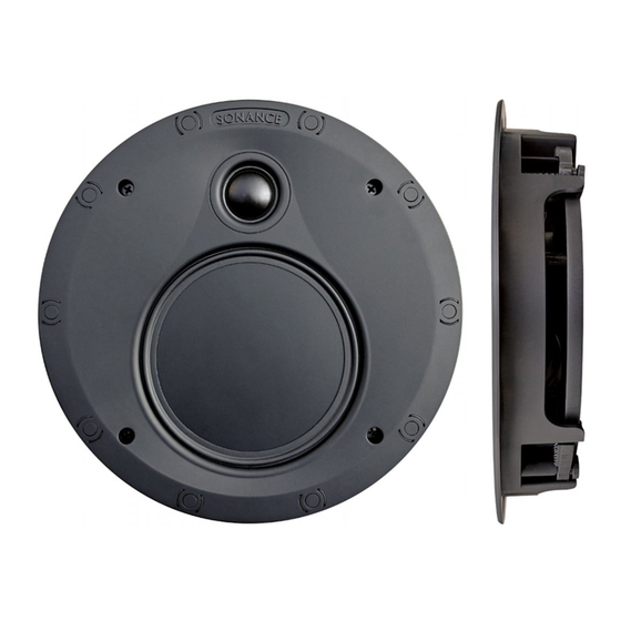
VP52R UTL ULTRA THIN-LINE SPEAKER
INSTRUCTION MANUAL
Box Contents
VP52R UTL
(1) Quickstart guide / cutout template
(2) Speakers
(2) Paintable grilles
Introduction
Thank you for purchasing Sonance Visual Performance
Series Ultra Thin-line Speakers.
Before Installation: Retro-fit
1. Determine the location for the speaker.
2. Perform an obstruction survey to be certain that there are
no studs, conduit, pipes, heating ducts, pocket doors
or air returns in the wall cavity that will interfere with
the speaker.
3. Position the included cutout template where the
speaker is to be located and pencil an outline on the
wall or ceiling.
• If you are unsure about obstructions, drill a small hole
in the center of the outline and insert a coat hanger wire
into the hole to feel-around for possible obstructions.
4. Cut the mounting hole using tools appropriate for the
construction, and run the speaker wires from the
mounting hole to the amplifier location.
NOTE: CONSULT LOCAL BUILDING CODES BEFORE RUNNING
SPEAKER WIRES THROUGH WALLS.
Installation
Sonance Visual Performance Series Speakers feature an
exclusive integral RotoLock
mounting directly into existing walls and ceilings.
1. Strip 1/4" – 1/2" (6mm – 13mm) of insulation from each
speaker lead. Twist the strands or tin the exposed wire
with solder to ensure that there are no stray strands.
NOTE: STRAY STRANDS THAT TOUCH EACH OTHER CAN CAUSE A
SHORT- CIRCUIT THAT CAN DAMAGE THE AMPLIFIER.
Connection Terminals
Figure 1: Connection Terminals
mounting system for quick
®
2. The speaker's connector posts are spring-loaded.
Push the top of each connector post down to open the
connector and insert the exposed wires into the holes in
the posts (see Figure 1).
3. The speaker's positive post is labeled with a red dot; the
negative post is labeled with a black dot.
4. After making all connections, double-check that you
connected amplifier "+" to speaker "+" and amplifier "–"
to speaker "–".
5. Make sure all the Roto-Lock toggle feet are retracted so
that they are tucked within the mounting hole's border.
Figure 2: Roto-Lock Toggle Feet Retracted
NOTE: THE ROTO-LOCK SYSTEM CAN ACCOMMODATE A WALL
MATERIAL THICKNESS OF 1 1/4" (32MM).
1
Advertisement

Subscribe to Our Youtube Channel
Related Manuals for Sonance VP52R UTL


Summary of Contents for Sonance VP52R UTL
- Page 1 Introduction 5. Make sure all the Roto-Lock toggle feet are retracted so that they are tucked within the mounting hole’s border. Thank you for purchasing Sonance Visual Performance Series Ultra Thin-line Speakers. Before Installation: Retro-fit 1. Determine the location for the speaker.
- Page 2 PAINTING THE GRILLES 6. Insert the speaker into the mounting hole (Figure 4) and tighten the four screws on the front of the speaker baffle. Sonance Visual Performance Series speaker grilles (Figure 5). completely cover the exposed speaker frame, so only the grilles (not the speakers themselves) require painting.
- Page 3 WARRANTY OF FITNESS FOR A PARTICULAR PURPOSE ARE SPECIFICALLY EXCLUDED. No one is authorized to make or modify any warranties on behalf of Sonance. The warranty stated above is the sole and exclusive remedy and Sonance’s performance shall constitute full and final satisfaction of all obligations, liabilities and claims with respect to the Product.
Need help?
Do you have a question about the VP52R UTL and is the answer not in the manual?
Questions and answers