Table of Contents
Advertisement
Quick Links
Application Guide
Top Fan Kit for FA09-FA12/D3h-D4h/E3h-E4h
iC7 Series Frequency Converters and VLT® FC Series Drives
1 Overview
1.1 Description
Top fan kits are used with iC7 Series FA09–FA12 Frequency Converters and VLT FC
The top fan assembly in FA09–FA10 and D3h–D4h frames requires 1 fan. The top fan assembly in FA11–FA12 and E3h–E4h frames
requires 2 fans. Top fans are secured under a grill or within a single or double fan housing.
Top Fan Replacement kits contain all parts required to replace 1 fan.
1.2 Kit Numbers
Use these instructions with the following kits.
Table 1: Top Fan Kits for iC7 Series FA09-FA12 Frequency Converters
Kit number
Description
176F3167
Top fan IP20 DC 80x38 mm
176F6636
Top fan IP20 DC 120x38 mm 48 V DC
®
Table 2: Top Fan Kits for VLT
FC Series D3h–D4h and E3h–E4h Drives
Kit number
176F3166
176F3167
1.3 Items Supplied
The following parts are contained in the kit.
Table 3: Items Supplied in Top Fan Kits
Item
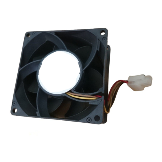
Fan
Installation instructions
Danfoss A/S © 2022.03
Description
Top fan IP20 DC 80x25 mm
Top fan IP20 DC 80x38 mm
®
Series D3h–D4h and E3h–E4h Drives.
Frame designation
FA09–FA10
FA11–FA12
Quantity
1
1
AN389655468601en-000101 / 130R0767 | 1
Advertisement
Table of Contents

Related Manuals for Danfoss 176F3167


Summary of Contents for Danfoss 176F3167
- Page 1 Top fan IP20 DC 80x25 mm 176F3167 Top fan IP20 DC 80x38 mm 1.3 Items Supplied The following parts are contained in the kit. Table 3: Items Supplied in Top Fan Kits Item Quantity Installation instructions Danfoss A/S © 2022.03 AN389655468601en-000101 / 130R0767 | 1...
- Page 2 N O T I C E QUALIFIED PERSONNEL Only qualified, Danfoss authorized personnel are allowed to install the parts described in these installation instructions. Disassembly and reassembly of the frequency converter must be done in accordance with the service guide.
- Page 3 Unplug the top fan cable connector. Pull the top fan cable through the cable access hole, freeing it from the cabinet. Remove 2 screws (T25) from opposite corners of the top fan grill. Danfoss A/S © 2022.03 AN389655468601en-000101 / 130R0767 | 3...
- Page 4 Fasten 2 screws (T25) in opposite corners of the grill, securing the top fan to the frequency converter. Position the front cover on the frequency converter, and fasten with 2 screws (T25). 4 | Danfoss A/S © 2022.03 AN389655468601en-000101 / 130R0767...
- Page 5 2.7 Removing the Top Fan and Double Fan Housing To remove the top fan and double fan housing, use the following steps. Refer to Illustration Unfasten 4 screws (T25) and remove the upper front cover of the frequency converter. Danfoss A/S © 2022.03 AN389655468601en-000101 / 130R0767 | 5...
- Page 6 Slide the double fan housing and 2 fans into position under the retaining clips. Secure 2 screws (T25) in the fan housing. Replace the upper front cover on the frequency converter, and fasten with 4 screws (T25). 6 | Danfoss A/S © 2022.03 AN389655468601en-000101 / 130R0767...
- Page 7 Top Fan Kit for FA09-FA12/D3h-D4h/E3h-E4h Application Guide Installation Danfoss A/S © 2022.03 AN389655468601en-000101 / 130R0767 | 7...
- Page 8 Danfoss reserves the right to alter its products without notice. This also applies to products ordered but not delivered provided that such alterations can be made without changes to form, fit or function of the product.
Need help?
Do you have a question about the 176F3167 and is the answer not in the manual?
Questions and answers