Table of Contents
Advertisement
Quick Links
Advertisement
Table of Contents

Related Manuals for Neptune RM-12P


Summary of Contents for Neptune RM-12P
-
Page 2: Table Of Contents
Important Note for System Connection 1. INTRODUCTION General Information ............................2 Front Panel .................................2 Rear Panel ................................4 2. INSTALLATION Commissioning of RM-12P..........................5 Capacitor Sequence ............................5 3. SETTINGS Operation Mode and Capacitor Power Settings ......................5 Target Cos Value Setting ............................6 Last Capacitor Step Number Setting ..........................7 Switching Program Setting ..........................8... -
Page 3: Safety Precautions
INTELLIGENT REACTIVE POWER MANAGEMENT RM-12P ATTENTION! Precautions for Safe Use and Installation Important Note for System Connection. Generator Input “Cosj2” Monitoring the measured temperature NOTE: RM-12P temperature measurement feature is optional. -
Page 4: Introduction
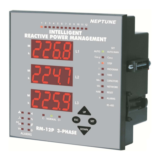
1.1 General Information 225.5 Measured Parameters : 228.7 223.4 DIMENSIONS Type PR16 (144x144) 1.2.a Button Functions 34.5 138.4 DOWN Excessive force can damage the device. Turn the screw into the terminals and tighten until the RM-12P is secured in place. - Page 5 INTELLIGENT REACTIVE POWER MANAGEMENT RM-12P 1.2.b Front Panel Functions 17. Capacitors / VAr Led 225.5 18. Network / VA Led 228.7 223.4 19. Reset / HAR Led 20. Alarm / h Led 21. RS-485 1. L1 2. L2 3. L3 22.
-
Page 6: Rear Panel
INTELLIGENT REACTIVE POWER MANAGEMENT RM-12P 1.3 Rear Panel CONNECTION DIAGRAM Generator Alarm Relay Input 110~250 V AC Warnings : Phase current should not be aqual to zero in order to let the device to sense the connection error. It is an obligation to connect a 3-phase capacitor for 1st step... -
Page 7: Installation
INTELLIGENT REACTIVE POWER MANAGEMENT RM-12P 2. INSTALLATION Warning: Device warns user by blinking (short ON, long OFF) led of the capacitor steps which will be switched on. Also device warns user by blinking (long ON, short OFF) led of the capacitor steps which will be switched off. -
Page 8: Target Cos Value Setting
INTELLIGENT REACTIVE POWER MANAGEMENT RM-12P 3.2 Target Cosj Setting 3.1.b Automatic Mode Setting Warning: If fast load variations exist together with Cosj 3.2.a Inductive Setting compensation capacitors, device can not detect correct connection at first time but after several attempts. If device can not finish this detection, C/k calculation can not be accomplished. -
Page 9: Last Capacitor Step Number Setting
INTELLIGENT REACTIVE POWER MANAGEMENT RM-12P 3.3 Last Capacitor Step Number Setting SAUE Note : When program 10 (PS-10) is selected, device detects steps without capacitors automatically. These steps are always switched off by device. In this case, only capacitor connected steps are functional. -
Page 10: Switching Program Setting
INTELLIGENT REACTIVE POWER MANAGEMENT RM-12P 3.4 Switching Program Setting SAUE a) Linear Operation: b) Rotational Switching: “ESC” “SAVE SEt yES” “SET” “ESC” P R O G R A M S E Q U E N C E c) PS-10 Program: linear 1.1.1.1.... - Page 11 INTELLIGENT REACTIVE POWER MANAGEMENT RM-12P 3.5.b Switch-Off Delay Time Setting “SET” “Delay” “UP/DOWN” (dELy t-of) “SET” (dELy t-on) “SET” “SET” “SET” “ESC” “ESC” SAUE SAUE “ESC” “SAVE SEt yES” “ESC” “SAVE SEt yES” “SET” “ESC” “SET” “ESC”...
-
Page 12: Connection And Power Value Settings
“RST” “on” “Setup:of” Note : When setup parameter is selected as “on” in Auto menu, after completing the measurement of capacitor powers according to the selected program, RM-12P continues to work in “setup:off” mode. (t-rC) 3 sec. “SET” “SET” “UP/DOWN”... - Page 13 INTELLIGENT REACTIVE POWER MANAGEMENT RM-12P 3.6.b Second Capacitor Step Setting “SET” “UP/DOWN” “C-02” “RST” “SET” “SET “UP/DOWN” “r” “S” “t” “rSt” “oF” “SET” “ESC Note : After automatic calculation of the capacitors, if “oF” is displayed Note : If PS-10 program is selected, capacitor powers can be set separately for each capacitor step.
-
Page 14: Current And Voltage Transformer Ratio Settings
INTELLIGENT REACTIVE POWER MANAGEMENT RM-12P 3 sec. “SET” “SET” “UP/DOWN” “ESC” (trF) (VA/TRF) SAUE “SET” “ESC” “SAVE SEt yES” “SET” “ESC” CAP C-03 CAP C-04 CAP C-05 “SET” CAP C-06 CAP C-07 CAP C-08 CAP C-09 CAP C-10 CAP C-11 CAP C-12 “SET”... - Page 15 INTELLIGENT REACTIVE POWER MANAGEMENT RM-12P 3.7.c Reactive Energy Calculation Method Setting 3.7.b Voltage Transformer Ratio Setting “345” Note : Take care that this value must be ratio but not VT primary or secondary value. Mechanical Energymeter Digital Energymeter Reactive Energy...
-
Page 16: Reset Setting
INTELLIGENT REACTIVE POWER MANAGEMENT RM-12P 3.8 Reset Settings 3.8.b Reactive/Active Ratio Reset Setting 3.8.a Alarm Reset Setting “yES” Note : When an alarm exists, alarm relay switches on. Also related led lights and alarm code is displayed. Even if alarm conditions do not exist, alarm relay still switches on. -
Page 17: Alarm Setting
INTELLIGENT REACTIVE POWER MANAGEMENT RM-12P 3.9 Alarm Settings 3.8.c Energy Counter Reset Setting voltage, reactive/active ratio, *temperature 3.9.a Over Voltage Alarm Setting “UP/DOWN” V> 3.9.a.a Over Voltage Setting “0” 3 sec. “SET” “SET” “UP/DOWN” (ALr) “UP/DOWN” “yES” “no” “SET” SAUE “SET”... - Page 18 INTELLIGENT REACTIVE POWER MANAGEMENT RM-12P “SET” “SET” “SET” “ESC” “SET” “ESC” Note : If over voltage value is set as “0”, this function is disabled. SAUE SAUE “ESC” “SAVE SEt yES” “SET” “ESC” “ESC” “SAVE SEt yES” “SET” “ESC” 3.9.a.c Switch On&Off Setting for Over Voltage Alarm Setting 3.9.a.b Over Voltage Delay Time Setting...
- Page 19 INTELLIGENT REACTIVE POWER MANAGEMENT RM-12P “SET” “SET” “UP/DOWN” (rAtE) “UP/DOWN” “on” “off” “SET” “ESC” SAUE “SET” “ESC” “SAVE SEt yES” “SET” “ESC” 3.9.b Reactive / Active Ratio Setting 3.9.b.a Capacitive Ratio Setting “SET” 3 sec. “SET” “SET” “ESC” “UP/DOWN” (Alr)
- Page 20 “ESC” “SAVE SEt yES” “SET” “ESC” “SET” “ESC” 3.9.c Temperature Alarm Settings Note : Temperature measurement feature is optional for RM-12P. 3.9.b.b Inductive Ratio Setting “0” 3.9.c.a Programming the Hihg Limit of Temperature Alarm 3 sec. “SET” “Alr rAtE CAP”...
- Page 21 INTELLIGENT REACTIVE POWER MANAGEMENT RM-12P 3.9.c.b Disabling the Temperature Alarm “SET” “SP-H” “ALr HEAt SP-H” (SP-L) “UP/DOWN” “SET” “SET” (SP-L) “SET” “SET” “ESC” “ESC” SAUE SAUE “ESC” “SAVE SEt yES” “ESC” “SAVE SEt yES” “SET” “ESC” “SET” “ESC”...
- Page 22 INTELLIGENT REACTIVE POWER MANAGEMENT RM-12P 3.9.c.c Switch On&Off Settings for Temperature Alarm 3.9.d Harmonic Setting “on” 3.9.d.a Over Voltage Harmonic Setting “of” 3 sec. “SET” “ALr HEAt SP-H” “STEP” “UP/DOWN” “UP/DOWN” (ALr) “SET” “SET” (ALr) “UP/DOWN” “on” “of” “SET” “ESC”...
- Page 23 INTELLIGENT REACTIVE POWER MANAGEMENT RM-12P “SET” (thdV) “SET” SAUE “SET” “ESC” “SAVE SEt yES” SAUE “SET” “ESC” 3.9.d.c Switch On&Off Settings for Harmonic Alarm “on” “of” “ESC” “SAVE SEt yES” “SET” “ESC” 3.9.d.b Harmonic Alarm Delay Time Setting “UP/DOWN” (StEP) “UP/DOWN”...
-
Page 24: Fan Relay Settings
“ESC” SAUE “SET” SAUE “ESC” “SAVE SEt yES” “SET” “ESC” 3.10 Fan Relay Settings Note: RM-12P temperature measurement feature is optional. 3.10.a Fan Relay Switched-on Value “ESC” “SAVE SEt yES” “SET” “ESC” 3 sec. 3.10.b Fan Relay Switching-off Value “SET”... -
Page 25: Computer Communication Setting
“ESC” “SAVE SEt yES” “SET” “ESC” 3.11 Computer Communication Settings (RS-485) Note : Computer communication feature is only available for “ESC” “SAVE SEt yES” RM-12P model. “SET” “ESC” 3.11.a Device Address Setting 3.11.b Baud Rate Setting 3 sec. “SET” “UP/DOWN”... -
Page 26: Password Activation And Change Settings
INTELLIGENT REACTIVE POWER MANAGEMENT RM-12P “SET” “UP/DOWN” “SET” “ESC” SAUE “UP/DOWN” “SET” “ESC” “ESC” “SAVE SEt yES” “SET” “ESC” SAUE 3.12 Password Activation and Change Settings Note : Factory set value for pin code is “1234” and also it is not activated. - Page 27 INTELLIGENT REACTIVE POWER MANAGEMENT RM-12P Note : If you do not save your changes, they will not be valid. Note : If you do not want to set another parameter, in order to quit from the menu, press “ESC” button sequencelly until “SAVE SEt yES”...
- Page 28 INTELLIGENT REACTIVE POWER MANAGEMENT RM-12P “SET” “ESC” SAUE “ESC” “SAVE SEt yES” “SET” “ESC”...
-
Page 29: Displaying Of Instantaneous Values
INTELLIGENT REACTIVE POWER MANAGEMENT RM-12P Total Cosj 4. DISPLAYING OF INSTANTANEOUS VALUES “DOWN” “UP” “DOWN” “SET” 1.000 “ESC” “Instantaneous Values” -.947 Cosj Voltages “UP/DOWN” “SET” “SET” 225.5 -.912 228.7 0.973 223.4 0.945 “SET” “SET”... -
Page 30: Total Cos Currents, Active Powers, Total Active Powers
INTELLIGENT REACTIVE POWER MANAGEMENT RM-12P Currents Active Powers “UP/DOWN” “UP/DOWN” “SET” “SET” 225.5 228.7 25.87 223.4 32.56 18.93 Total Active Powers “SET” “DOWN” Note : The dot at the most right digit of the third display represents that displayed value is export active power value. -
Page 31: Reactive Powers, Total Reactive Powers, Apparent Powers, Total Apparent Powers, Total Apparent Powers
INTELLIGENT REACTIVE POWER MANAGEMENT RM-12P Reactive Powers Apparent Powers “UP/DOWN” “UP/DOWN” “SET” “SET” 225.5 225.5 228.7 228.7 223.4 223.4 “SET” “SET” Total Reactive Powers Total Apparent Powers “DOWN” “DOWN” Note : The dot at the most right digit of the third display represents that displayed value is capacitive reactive power value. -
Page 32: Active Import Energy, Active Export Energy, Inductive Reactive Energy, Capacitive Reactive Energy, Temperature, Error Codes
INTELLIGENT REACTIVE POWER MANAGEMENT RM-12P Active Import Energy Capacitive Reactive Energy “E” “UP/DOWN” “I” E-00 1-20 4035 3385 386.2 706.8 Active Export Energy “DOWN” “E” Note: When you reset reactive / active ratio, the value in the first display is reset and the value is updated continiously. -
Page 33: Appendix
INTELLIGENT REACTIVE POWER MANAGEMENT RM-12P ALARM CODES DESCRIPTION REASON Angle degree between phase voltages doesn’t equal to 120° Neutral and Voltage terminal connections may be wrong Reverse phase sequence Voltage terminal connections may be in counter clockwise direction One or more phase voltages don’t exist... -
Page 34: Computer Communication (Modbus Rtu)
INTELLIGENT REACTIVE POWER MANAGEMENT RM-12P REGISTER TABLE REGISTER TABLE ADDRESS (HEX) PARAMETER FORMAT MULTIPLIER UNIT FUNCTION... - Page 35 INTELLIGENT REACTIVE POWER MANAGEMENT RM-12P REGISTER TABLE ADDRESS (HEX) PARAMETER FORMAT MULTIPLIER UNIT FUNCTION...
- Page 36 INTELLIGENT REACTIVE POWER MANAGEMENT RM-12P REGISTER TABLE ADDRESS (HEX) PARAMETER FORMAT MULTIPLIER UNIT FUNCTION...
- Page 37 INTELLIGENT REACTIVE POWER MANAGEMENT RM-12P REGISTER TABLE ADDRESS (HEX) PARAMETER FORMAT MULTIPLIER UNIT FUNCTION...
- Page 38 INTELLIGENT REACTIVE POWER MANAGEMENT RM-12P REGISTER TABLE ADDRESS (HEX) PARAMETER FORMAT MULTIPLIER UNIT FUNCTION...
-
Page 39: Capacitor Calculation Table
INTELLIGENT REACTIVE POWER MANAGEMENT RM-12P CAPACITOR CALCULATION TABLE... -
Page 40: Technical Features
INTELLIGENT REACTIVE POWER MANAGEMENT RM-12P Technical Features Factory Set Values Optional...
Need help?
Do you have a question about the RM-12P and is the answer not in the manual?
Questions and answers