
Related Manuals for Neptune DUCATI REGO


Summary of Contents for Neptune DUCATI REGO
- Page 1 REGO Instruction Manual Automatic Reactive Power Controller Revision-0 Firmware - 4.01 March, 2004...
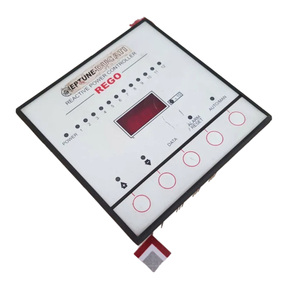
- Page 2 DUCATI energia REGO POWER REMOT VAC 5 DUCATI energia MAINS CONNECTION OPER.TYPE C.T.POST. 230V 400V REACTIVE POWER CONTROLLER REGO MADE IN TIALY REACTIVE POWER CONTROLLER CT./ 400V 230V ALARM AUTO DATA RESET Fig-1 - Front and Rear panel of Rego-5 RS-485 MAX250V 6A DUCATI...
- Page 3 MAINS -380-415V T/23 S/L2 R/L1 REGO CT../5A FF1 CONNECTION 400V (V2) 230V (V1) REGO CT../5A FF2 CONNECTION 400V (V2) 230V (V1) CT../5A F-n CONNECTION Only for 400V (V2) 230V (V1) single phase network USE 200mA FUSE FOR LOAD VOLTAGE INPUTS Fig.-3 - Mains Connection MAINS T/23...
-
Page 4: Simplified Diagram Relative To First Powering Up
Simplified Diagram relative to First Powering up SELF- ACQUISITION MANUAL PROGRAMMING POWER THE CONTROLLER DISPLAYALTERNATELY SHOWS “IL” AND “- - -” ENTER “IL” PARAMETER MAINS C.T. RATIO (e.g. w/ C.T. 200/5 enter 40) “+” AND “-” TO CHANGE THE PARAMETER AND “DATA” KEY TO CONFIRM “FAS”... -
Page 5: Table Of Contents
CONTENTS SIMPLIFIED DIAGRAM RELATIVE TO FIRST POWERING UP ... SAFETY ... GENERAL DESCRIPTION ... HOW IT WORKS ... MAINS CONNECTION ... INSTRUCTIONS FOR INSTALLING THE. CT.... POWERING UP FOR THE FIRST TIME ... SUBSEQUENT STARTUPS ... TESTING CONTROLLER PERFORMANCE ... -
Page 6: Safety
2) SAFETY NOTE: The front panel of REGO features a series of keys This automatic power factor correction controller was for accessing functions and programming; some functions manufactured and tested in conformity with current standards and are activated by pressing a combination of 2 keys: in this left the factory in perfect conditions of technical safety. -
Page 7: Powering Up For The First Time
TRANSFORMER ROOM T.A. C.T. INSTALLATION CORRECT MAIN SWITCH T.A. C.T. INSTALLATION CORRECT T.A. C.T. INSTALLATION T.A. INCORRECT C.T. DEDICATED SWITCH FOR POWER INSTALLATION FACTOR INCORRECT CORRECTION SYSTEM LOADS Fig.-5 - Positioning of C.T. (7) POWERING UP FOR THE FIRST TIME The REGO regulator behaves differently the first time it is started up since it will need the IL parameter (mains C.T. -
Page 8: Subsequent Startups
NOTE: if the incoming current is insufficient (less than 200mA), At this point, the controller no longer requires any type of setting REGO cannot determine its direction and will stand by in this and will be ready for perfect operation: it will alternately display status until current is supplied. - Page 9 DO NOT CHANGE THIS PARAMETER IF THE CONTROLLER = a new automatic acquisition procedure will be carried out. IS INSTALLED ON A DUCATI ENERGIA POWER FACTOR CORRECTION SYSTEM. Press DATA to go on to the next parameter The capacitor steps will be switched on and measured in 10.4 “IL”...
-
Page 10: Display Of Measurements
SEMI-GEOMETRIC LOGIC Parameter Description Range Default It is identified by the code 1:2:2 and the power of the first bank (10.1) Measured mains 50 or 60 Hz must be half that of the others, which must all be equal. The first Freq. -
Page 11: Displaying The Powers Of Single Steps
press to choose the status of the relay you want to set in 12.5 DISPLAYING THE COUNTER OF TOTAL OPERATIONS the manual operating mode; press the DATA key to display the PERFORMED BY EACH RELAY status of the subsequent relay. After viewing the status of the last relay, press the DATA key to exit this function. -
Page 12: Total Resetting Of Setup Parameters
13.2 OVERVOLTAGE SIGNAL This signal is activated when the controller measures a supply voltage exceeding the maximum allowed by the transformer (230 +19%; 400 +19%) for longer than 30 seconds. To set the appropriate operating mode for correcting the power factor of generators, press the key: the word “... -
Page 13: Protection Against Mains Voltage Dips And Drops
After 30 minutes all these actions will be cleared and the controller 14) HIDDEN MENU will automatically resume operation (auto-reset status A.r. Some REGO parameters are present in the hidden menu. These though the incident will continue to be signaled via the display, settings may be accessed by the user only when setting the C.T. -
Page 14: Troubleshooting
When no bank is switched on, the controller displays a capacitive Parameter Description Range Default cosø. (negative cosø.) Temperature threshold (°C) 5...50 REGO7-12 for tripping fan activation. Time (in seconds) of 5...255 unavailability of a step for re-activation. Always wait for - The controller displays a cos. - Page 15 Measurement and control data Type of voltage and current true effective value ( true RMS) measurement Power factor control 0.80 inductive ÷ 0.80 capacitive Step re-connection time lag 5...255s Relay outputs Number of outputs 5/7/12 Contact status Nominal contact capacity 5A - 250V Voltage rating 250Vac...
Need help?
Do you have a question about the DUCATI REGO and is the answer not in the manual?
Questions and answers