
Related Manuals for Kramp KRED-D


Summary of Contents for Kramp KRED-D
- Page 1 USER GUIDE for solenoid operated proportional valves UNIVERSAL ELECTRONIC DRIVER TYPE KRED kramp...
-
Page 2: Key Features
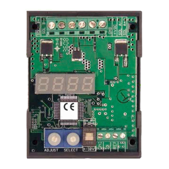
Maximum ramp time: 99,5 s the need of special tools or programming devices. Linearity: 40-450 Hz A 4 digit led display shows all the necessaries informations. Operating Temperature: -40 .. 80 °C Versions: Mounting: DIN rail (open) KRED-S is for single solenoid proportional valves KRED-D is for double solenoid proportional valves 3 SET-UP PROCEDURE Available input selection KRED-S Available input selection KRED-D DIP Switch in ON/UP position "in" :10 -->(0 to 10V) ** default "in" :10 -->(0 to 10V) ** default "in" :5 --> (0 to 5V) "in" :5 --> (0 to 5V) "in" :420 --> ( 4 to 20 mA) "in" :420 --> ( 4 to 20 mA) DIP Switch in OFF/Down position "in" : -10 -->(-10 to 10V) 1. At power up, the display will show either the output current signal or the input signal (Default display setting shows the output signal). The decimal point will be flashing. 2. Rotate SELECT to enter the set-up mode. Parameter abbreviation is indicated on the display 3. When you reach the setting you want to modify, rotate ADJUST up or down to the desired value. -
Page 3: Setting Ranges
5 - Voltage signal 0 - 5 V 20 - Voltage signal 0 - 10 V 420 - Current signal 4 - 20 mA DISPLAYED SIGNAL FOR TROUBLESHOOTING: 0 - Command signal [V] or [mA] 1 - Output signal [A] **Flashing decimal point is an indicator for present display mode** - Fast flashing decimal point, several flashes per second indicates di=0 - Slow flashing decimal point, 1 per second indicates di=1 - No flashing decimal point or no decimal point indicates display in SETTING/ADJUST SAVE SETTINGS RESET FACTORY PARAMETERS (see note 2) ERROR DETECTION STATE, short circuit, reverse polarity protection and detection: 0 - Error 0 - No errors 1 - Error 1 - Overcurrent in driver likely due to short circuit in Solenoid 2 - Error 2 - Current exceeding 20 mA in 4-20 mA input mode CLEAR ERROR, clear driver or error state (see note 2) NOTE 1 When adjusting the HI and LO parameters, note the HI parameter value cannot be adjusted below the LO parameter value as well the LO parameter value cannot exceed the HI parameter value. NOTE 2 Adjust Parameter value up past 9 to operate this command setting NOTE 3 * in KRED-D parameter will be aHi or bHi (as example) when a solenoid or b solenoid is configured 03/2016 Universal electronic driver type KRED for solenoid operated proportional valves... - Page 4 6 SChEMATICS KRED-S 1) EXTERNAL INPUT SIGNAL CONNECTION (” in” set to ”10”) 2) POTENTIOMETER CONNECTION (” in” set to ”5”) 3) RAMP UP & DOWN ONLY OPERATION (” in” set to ” 5”) 4) EXTERNAL INPUT SIGNAL CONNECTION 4-20 mA (”...
- Page 5 SChEMATICS KRED-D 1) EXTERNAL INPUT SIGNAL CONNECTION 2) POTENTIOMETER CONNECTION (” in” set to ”10”) (” in” set to ”5”) 3) EXTERNAL INPUT SIGNAL CONNECTION (” in” set to ”-10”) 5) EXTERNAL INPUT SIGNAL CONNECTION 4) TWO WIRE TRANSMITTER INPUT CONNECTION (”...
- Page 6 7 ADjUSTMENT KRED Adjustment of Maximum: Adjustment of minimum (Low) / parameter „Lo“ (High) / parameter „Hi“ Maximum Current output 0,00 - 2,99 A Maximum Current output 0,20 - 3,00 A 3.00 3.00 3.00 2.00 2.00 1.00 1.00 0.00 0.00 5 or 10 V 5 or 10 V Command signal [V or mA]...
- Page 7 ADjUSTMENT KRED This product has been designed and tested to meet specific standards outlined in the EMC 2004/108/EC Emission: EN 61000-6-4:2007 Immunity: EN 61000-6-2: 2005, EN 61000-4-2, EN 61000-4-4, EN 61000 4-6 03/2016 Universal electronic driver type KRED for solenoid operated proportional valves...
Need help?
Do you have a question about the KRED-D and is the answer not in the manual?
Questions and answers